
Method and apparatus for dynamically allocating bandwidth utilization in a packet telephony system

a packet telephony system and bandwidth utilization technology, applied in data switching networks, time-division multiplexing selection, multiplex communication, etc., can solve the problem that conventional packet telephony systems do not dynamically adjust the codec selection for a given connection based on network conditions, and achieve the effect of maximizing the likelihood of the recipient devi

Inactive Publication Date: 2006-03-28
LUCENT TECH INC
View PDF15 Cites 22 Cited by
  • Summary
  • Abstract
  • Description
  • Claims
  • Application Information

AI Technical Summary

Benefits of technology

[0010]According to another aspect of the invention, the network monitoring agent notifies one or both of the devices associated with each connection of changes in the encoding scheme. Generally, both devices must change the encoding algorithm at the same time, to ensure proper decoding of received packets. In one implementation, the initiating device inserts a notification in a field of the packet header to inform the recipient device that subsequent packets will be encoded with a different specified encoding algorithm, until further notice. Thereafter, the recipient device can load the appropriate codec to properly decompress and decode the received packets. In a further variation, the notification of a codec change (or the current codec) can be repeatedly included in the packet header at periodic intervals, or repeated a predetermined number of times in successive packets, to maximize the likelihood that the recipient device gets at least one notification.

Problems solved by technology

While conventional packet telephony systems effectively select an appropriate codec for a given media type to produce satisfactory compression, conventional packet telephony systems do not dynamically adjust the codec selection for a given connection based on network conditions.

Method used


Image

  • Method and apparatus for dynamically allocating bandwidth utilization in a packet telephony system
  • Method and apparatus for dynamically allocating bandwidth utilization in a packet telephony system
  • Method and apparatus for dynamically allocating bandwidth utilization in a packet telephony system

Examples


Embodiment Construction

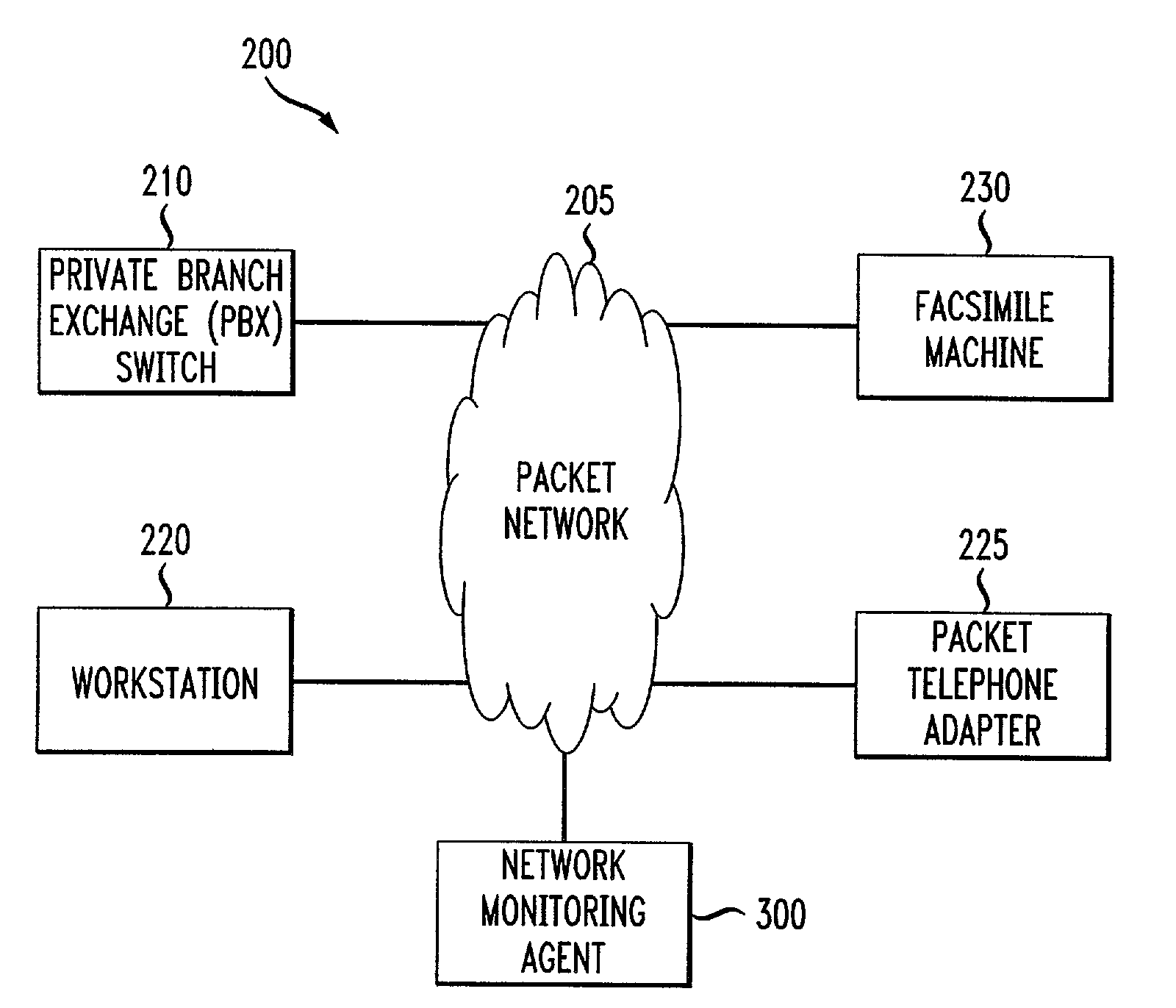
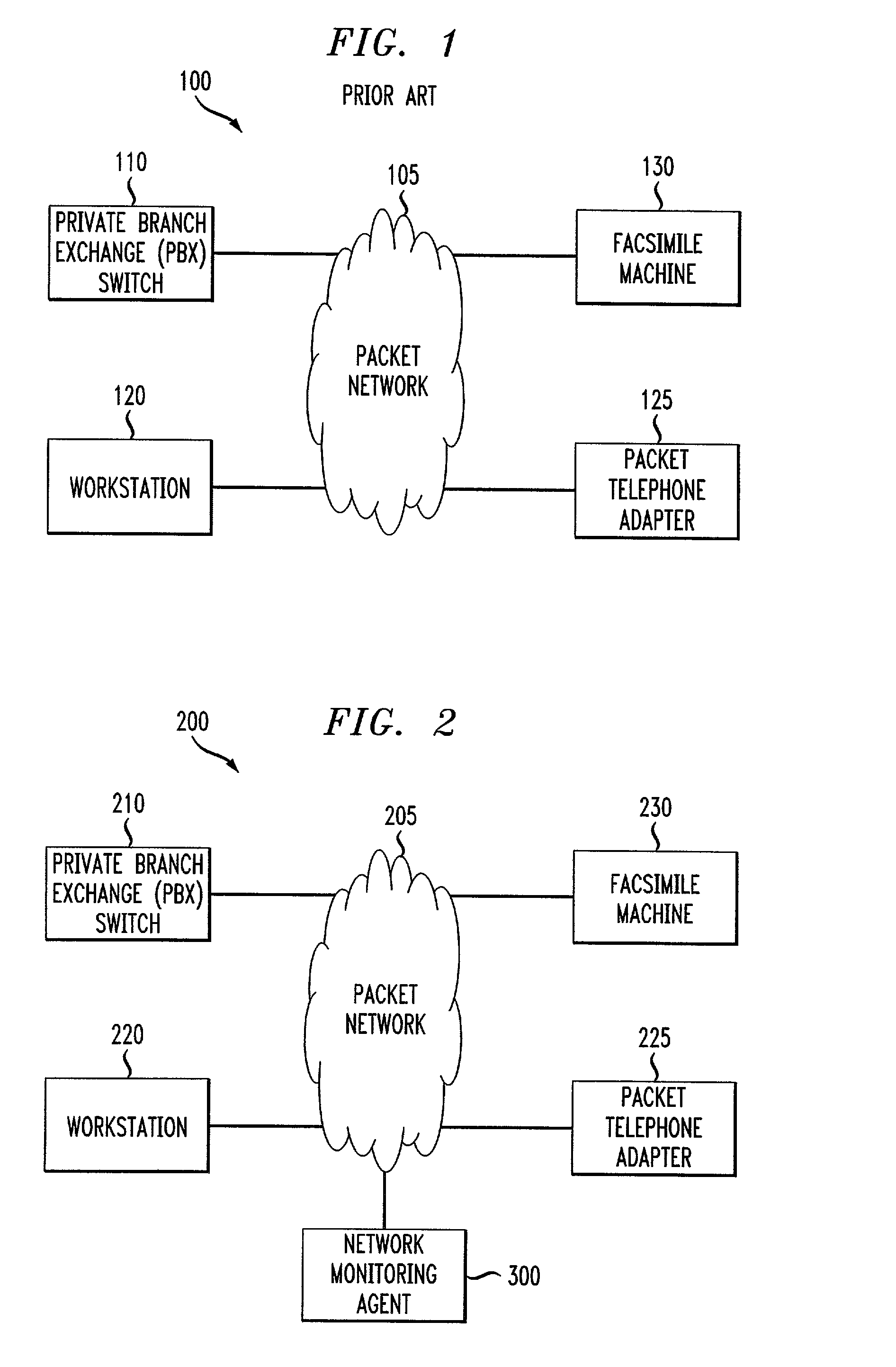
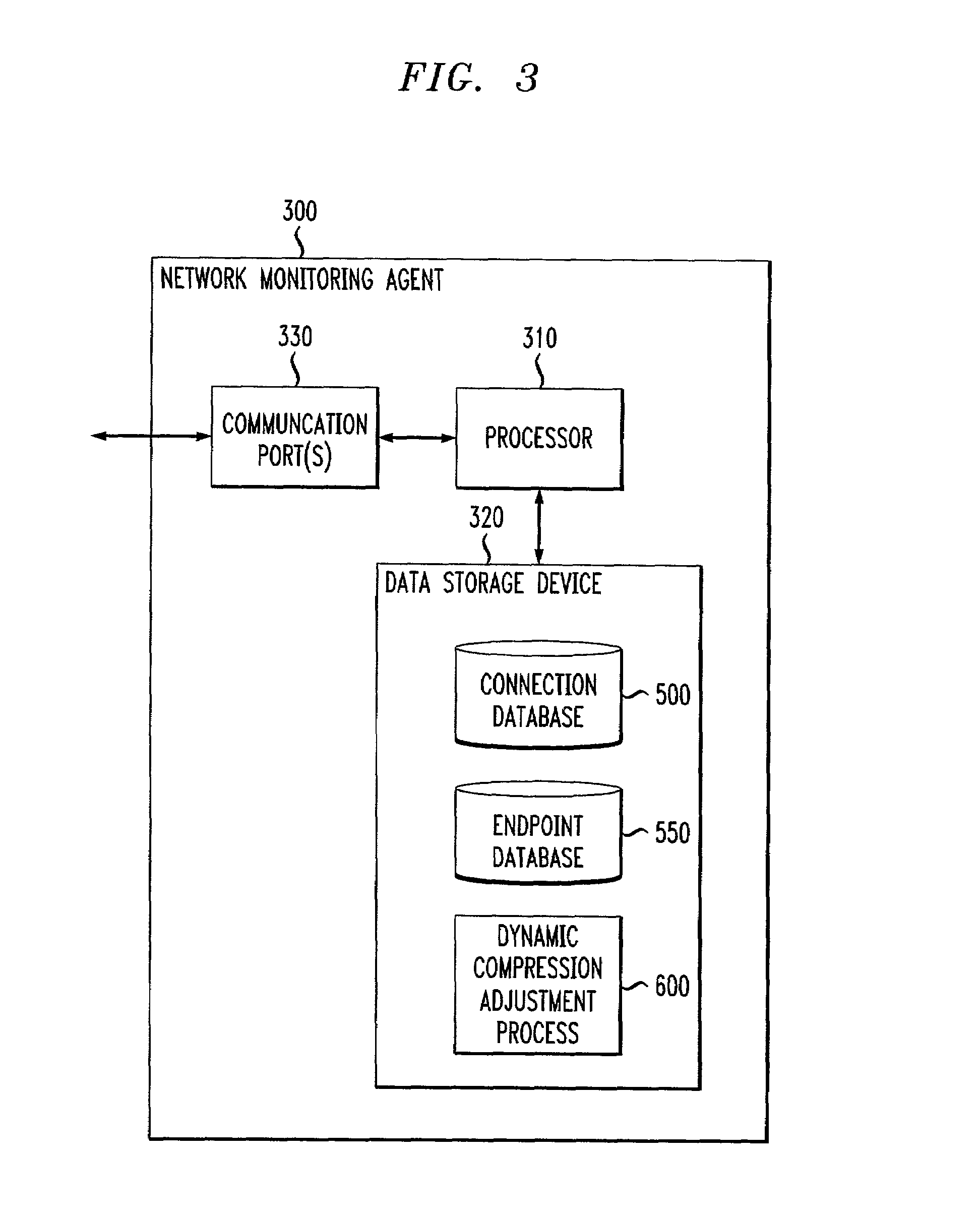
[0019]FIG. 2 illustrates a multimedia packet telephony system 200 in accordance with the present invention. The, present invention provides a network monitoring agent 300, discussed below in conjunction with FIG. 3, that monitors network conditions, such as traffic volume, and determines when to dynamically adjust the level of compression for one or more connections in order to maximize the total number of possible connections, while maintaining a desired level of quality.

[0020]According to one feature of the present invention, the network monitoring agent 300 selects a compression standard based on current network traffic volume. At times of lighter network traffic, a compression standard that provides a lower degree of compression and a higher quality level is selected. Likewise, as network traffic increases, a compression standard that provides a higher degree of compression, although at a lower quality level, is selected in order to maximize the network utilization. As network b...


PUM


Abstract

A network monitoring agent is disclosed that monitors network conditions, such as traffic volume, and determines when to dynamically adjust the encoding scheme for one or more connections. The network monitoring agent can select an encoding standard based on, for example, current network traffic volume, network error characteristics, time of day or day of week. In the illustrative network traffic implementation, an encoding standard that provides a lower degree of compression and a higher quality level is selected at times of lighter network traffic. Likewise, as network traffic increases, an encoding standard that provides a higher degree of compression, although at a lower quality level, is selected in order to maximize the network utilization. The network monitoring agent notifies one or both of the devices associated with each connection of changes in the encoding scheme. Generally, both devices must change the compression algorithm at the same time, to ensure proper decoding of received packets. The initiating device inserts a notification in a field of a predefined number of packet headers to inform the recipient device that subsequent packets will be encoded with a different specified encoding algorithm, until further notice. Thereafter, the recipient device can load the appropriate codec to properly decompress and decode the received packets.

Description

CROSS-REFERENCE TO RELATED APPLICATION[0001]The present invention is related to United States patent application entitled “Method and Apparatus for Dynamically Exchanging Data Among Participants to a Conference Call,” having Ser. No. 09 / 329,463, filed Jun. 10, 1999, filed contemporaneously herewith, assigned to the assignee of the present invention and incorporated by reference herein.FIELD OF THE INVENTION[0002]The present invention relates generally to packet telephony systems, and more particularly, to methods and apparatus for allocating the bandwidth utilization in such packet telephony systems.BACKGROUND OF THE INVENTION[0003]Communication networks are used to transfer information, such as data, voice, text or video information, among communication devices, such as packet telephones, computer terminals, multimedia workstations, and videophones, connected to the networks. A network typically comprises nodes connected to each other, and to communication devices, by various links...

Claims


Application Information

Patent Timeline
Patent Type & Authority Patents(United States)
IPC IPC(8): H04J3/22H04M3/00H04L12/56H04L12/64H04Q11/04
CPCH04L12/6418H04Q11/0478H04L2012/5616H04L2012/5635H04L2012/5636H04L2012/6475H04L2012/6481H04L2012/6497H04L2012/5671
Inventor BAUER, ERIC JONATHANLAM, YUK-MING PETERORLEANSKI, JOHN
Owner LUCENT TECH INC
Learn More