
Servo information write method, servo control method, data storage device, and program

a technology of servo information and write method, applied in the direction of digital recording, magnetic recording, recording/reproducing/erasing method, etc., can solve the problem that the processing required for propagation-pattern-based servo control cannot be completed, and the servo information write must be performed in a clean room. problem, to achieve the effect of increasing accuracy

Inactive Publication Date: 2006-03-28
HITACHI GLOBAL STORAGE TECH NETHERLANDS BV
View PDF3 Cites 21 Cited by
  • Summary
  • Abstract
  • Description
  • Claims
  • Application Information

AI Technical Summary

Benefits of technology

[0011]It is a further object of the present invention to enhance the head positioning control accuracy.
[0012]The present invention proposes positioning a magnetic head and performing a self servo write in accordance with a servo pattern written on a disk-type storage medium instead of a propagation pattern written on a disk-type storage medium. The present invention also proposes enhancing the head positioning accuracy by making corrections in accordance with the propagation pattern.
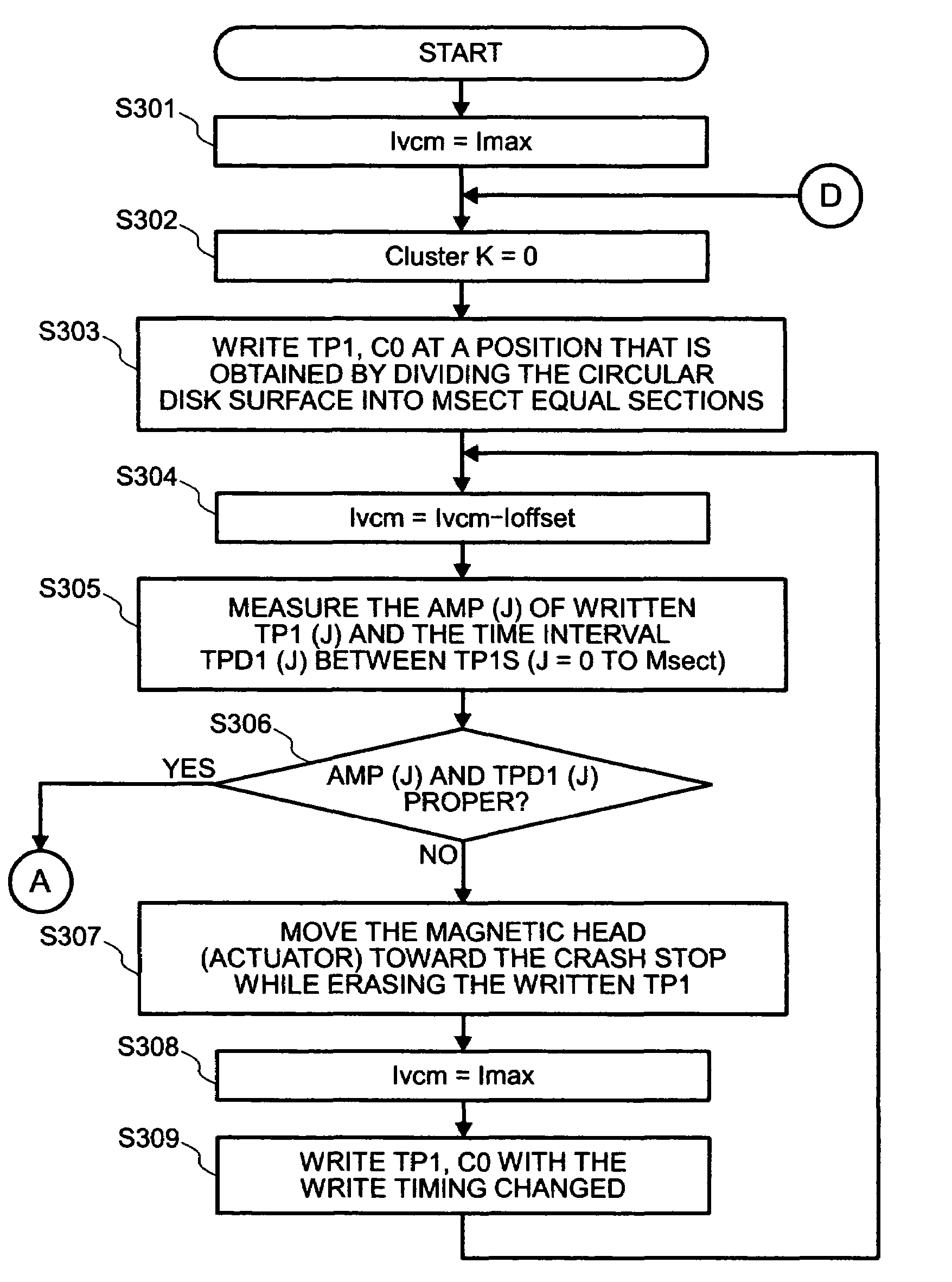
[0013]More specifically, the servo information write method of the present invention comprises two steps. The first step positions an actuator on which a composite head containing a read head and a write head is mounted while the actuator is in contact with a crash stop, and causes the write head to write a servo pattern and a propagation pattern onto a disk-type storage medium. The second step is performed, when the servo pattern written on the disk-type storage medium by the write head can be detected by the read head, in order to position the write head by means of servo control based on the detected servo pattern and cause the write head to further write a servo pattern and a propagation pattern onto the disk-type storage medium.
[0021]The present invention also proposes controlling the positions of a read head and a write head with increased accuracy by establishing the correlation between a position error signal, which is obtained by reading a servo pattern, and the positions of the read head and write head.
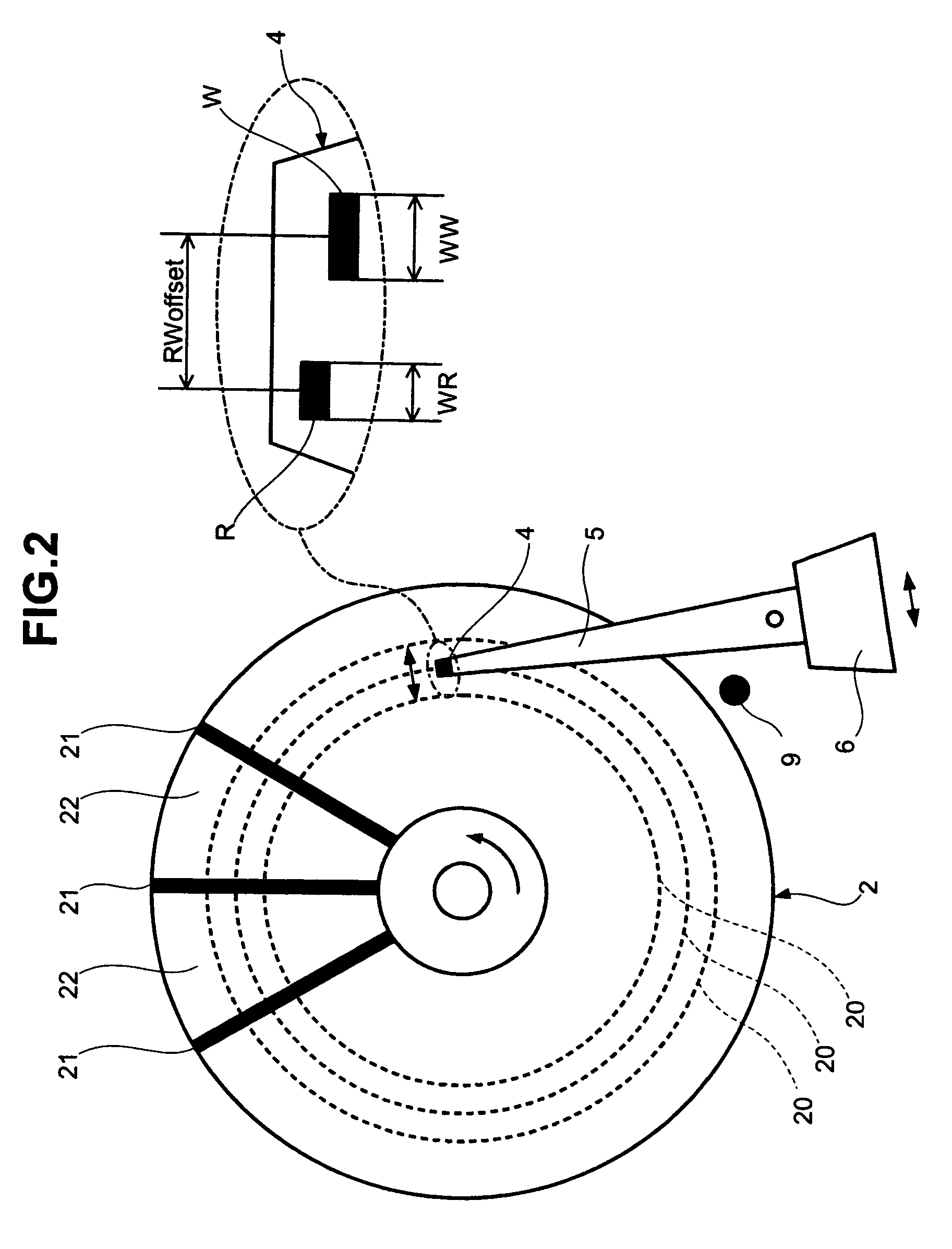
[0023]The second step for the above servo control method uses a read / write offset which is the distance between the read head and the write head. Further, this second step causes the write head to write a measurement pattern at a position other than the position for the servo pattern on the disk-type storage medium, causes the read head to detect a profile of the measurement pattern written on the disk-type storage medium, and linearizes the relationship between the position error signal and the read head position in accordance with the detected measurement pattern.
[0024]The data storage device of the present invention comprises two servo first means. The first servo write means positions an actuator on which a composite head containing a read head and a write head is mounted while the actuator is in contact with a crash stop, and causes the write head to write a servo pattern and a propagation pattern onto a disk-type storage medium. The second servo write means positions, when the servo pattern written on the disk-type storage medium by the write head can be detected by the read head, the write head by means of servo control based on the detected servo pattern and causes the write head to further write a servo pattern and a propagation pattern onto the disk-type storage medium.

Problems solved by technology

However, the use of the above methods makes it necessary to write clock data onto a magnetic disk with the clock head or press the push pin against the actuator.
Therefore, the use of the above methods imposes a restriction that the servo information write must be performed within a clean room.
Processing required for propagation-pattern-based servo control cannot be completed by using a hard disk controller (HDC) and MPU (microprocessing unit) built in a hard disk drive as well as software.

Method used


Image

  • Servo information write method, servo control method, data storage device, and program
  • Servo information write method, servo control method, data storage device, and program
  • Servo information write method, servo control method, data storage device, and program

Examples


Embodiment Construction

[0049]The embodiments of the present invention will now be described in detail with reference to the accompanying drawings.

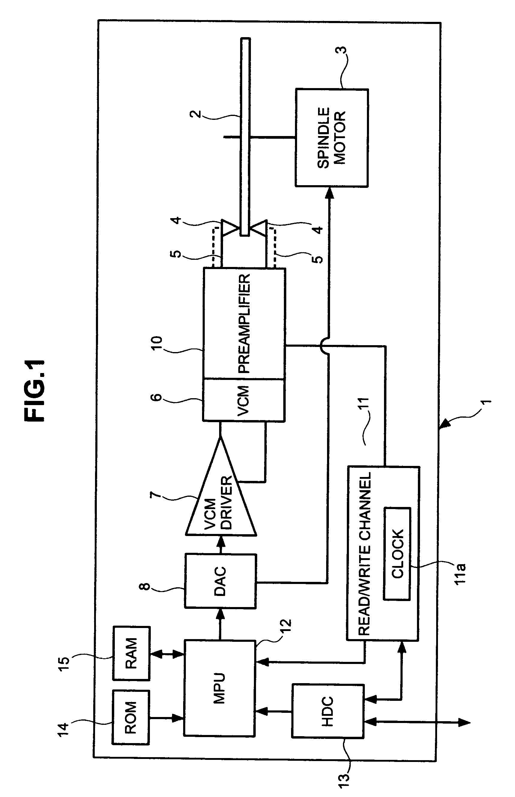
[0050]FIG. 1 is a block diagram that illustrates major components of a hard disk drive 1. FIG. 2 is a top view that illustrates the major components of the hard disk drive 1. The hard disk drive 1 includes a magnetic disk 2, a spindle motor 3, a magnetic head 4, an actuator 5, a VCM (voice coil motor) 6, a VCM driver 7, a DAC (digital / analog converter) 8, a crash stop 9, a preamplifier 10, a read / write channel 11, an MPU (microprocessing unit) 12, an HDC (hard disk controller) 13, a ROM (read-only memory) 14, and a RAM (random access memory) 15, and is connected via the HDC 13 to a computer or like device, which is not shown. Although one or more units of the magnetic disk 2 are installed as needed, FIG. 1 shows an example in which only one unit of the magnetic disk 2 is installed.

[0051]While the hard disk drive 1 is operating, the magnetic disk 2, which is used...


PUM

PropertyMeasurementUnit
timeaaaaaaaaaa
current flowaaaaaaaaaa
distanceaaaaaaaaaa

Abstract

A servo system wherein a read head R detects a servo pattern that is written on a magnetic disk by a write head W. Position control of the write head W is exercised in accordance with the detected servo pattern, and the read head R detects a propagation pattern that is written on the magnetic disk by the write head W. Position of the write head W is corrected in accordance with the detected propagation pattern.

Description

FIELD OF THE INVENTION[0001]The present invention relates to a servo information write method, servo control method, data storage device, and program for a storage medium, and more particularly to a servo information self-write method, servo control method, data storage device, and program.BACKGROUND OF THE INVENTION[0002]Hard disk drives, which are widely used as a data storage device for computers and like devices, include a magnetic head for reading user data stored on a magnetic disk or writing user data onto a magnetic disk. The magnetic head is mounted on an actuator that is oscillated by a VCM (voice coil motor). When the magnetic head reads or writes user data, the actuator is driven to move the magnetic head to a specific track (target track) for positioning purposes. Magnetic head positioning control is exercised in accordance with servo information stored on a magnetic disk to move the magnetic head to a specified position. In line with recording density improvement, hard...

Claims


Application Information

Patent Timeline
Patent Type & Authority Patents(United States)
IPC IPC(8): G11B21/02G11B21/08G11B5/596G11B21/10
CPCG11B21/106G11B5/59633
Inventor ISERI, KAORUKURODA, TAKASHIMATSUBARA, NOBUYAOGASAWARA, KENJISAI, FUMINORIYANAGISAWA, HIROSHI
Owner HITACHI GLOBAL STORAGE TECH NETHERLANDS BV
Learn More