
Bearing assembly with temperature sensor

a technology of temperature sensor and bearing assembly, which is applied in the direction of heat measurement, instruments, transportation and packaging, etc., can solve the problems of reducing the accuracy of temperature detection, and reducing the number of components used. , to achieve the effect of simple and easy security

Inactive Publication Date: 2006-03-28
SONY CORP +1
View PDF12 Cites 15 Cited by
  • Summary
  • Abstract
  • Description
  • Claims
  • Application Information

AI Technical Summary

Benefits of technology

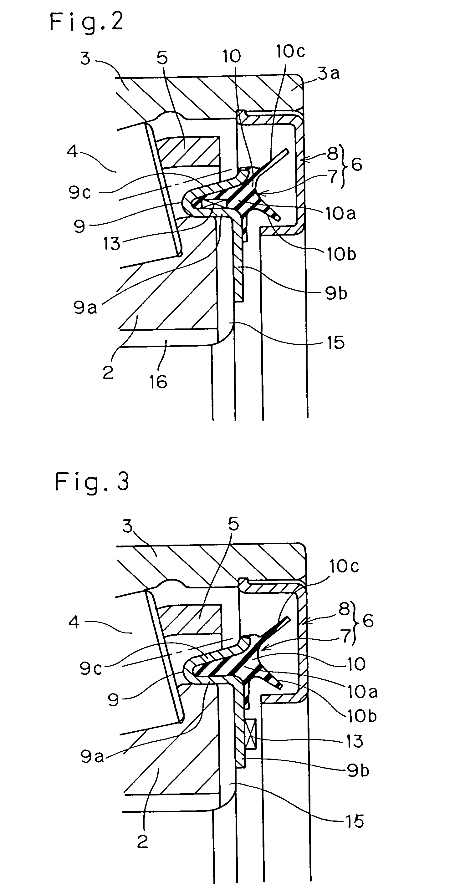
The present invention provides an improved bearing assembly with a temperature sensor built in, which increases the accuracy of detecting abnormal temperatures, reduces the number of component parts, and increases productivity. The temperature sensor is secured to the sealing member, which is a part of the bearing assembly and measures the temperature inside the assembly. The sealing member is integrated with the bearing assembly, reducing the number of component parts. The temperature sensor is secured to the sealing member during manufacture, resulting in high productivity. The sealing member includes a core metal and an elastic member integrated together, effectively and efficiently conducting the temperature of the bearing ring to the temperature sensor. The temperature sensor is fixed to the sealing member by means of an integral molding of the elastic member with the core metal, ensuring stable securement. The temperature sensor is a chip-type laminar thermistor, which is compact, highly sensitive, and easily accommodated by the sealing member.

Problems solved by technology

It has, however, been found that with the sensor-equipped bearing assembly now in use, the following problems have been involved:(1) Since the temperature sensor used therein does not detect the temperature of the bearing assembly directly, the timing at which the abnormal temperature is detected tends to be retarded, resulting in that at the time of actual detection of the abnormal temperature, the bearing assembly would have already damaged detrimentally.
Once this occurs, determination of a cause of the abnormal temperature would be virtually futile.(2) Since the temperature sensor is a member separate from the bearing assembly, a space for installation thereof is required within a limited space available in the bearing assembly.(3) Because of the temperature sensor being a member separate from the bearing assembly, the number of component parts in the bearing assembly as a whole tends to increase, resulting in complicated and time-consuming servicing operations.
While it is a general practice to replace the bearing assembly regularly during a cycle checkout, replacement of the temperature sensor is also required separate from and independently of the replacement of the bearing assembly and, accordingly, complicated and time-consuming procedures are required in performing a job of replacement.(4) Considering that the temperature sensor is secured to an outside of a bearing box forming a part of the bearing assembly, the temperature sensor is susceptible to damage or malfunctioning by collision with scattered stones and / or rocks, resulting in false generation of an erroneous signal indicative of detection of the abnormal temperature.
However, since the temperature sensor 63 is designed to be carried by the inner race which is one of the bearing rings forming the bearing assembly, mounting of the temperature sensor on the inner race is difficult to achieve, resulting in reduction in productivity.

Method used


Image

  • Bearing assembly with temperature sensor
  • Bearing assembly with temperature sensor
  • Bearing assembly with temperature sensor

Examples


Embodiment Construction

[0029]Preferred embodiments of the present invention will now be described with reference to the accompanying drawings.

[0030]Referring first to FIG. 1, there is shown, in a fragmentary longitudinal sectional representation, a bearing assembly having a temperature sensor built therein according to a first preferred embodiment of the present invention. This bearing assembly is shown in FIG. 4 as used in rotatably supporting a railway vehicle wheel. The bearing assembly 1 shown therein is of an outer race rotating type and includes two bearing rings which are an inner race 2 and an outer race 3, respectively. Of these bearing rings, the inner race 2 serves as a stationary bearing ring and is fixedly mounted on an axle 11 as shown in FIG. 4. The outer race 3 serving as a rotary bearing ring is fixedly mounted inside a hub of the railway vehicle wheel 12.

[0031]In a first embodiment shown in FIG. 1, the bearing assembly 1 includes a plurality of rolling elements 4 rotatably retained by a ...


PUM

PropertyMeasurementUnit
temperatureaaaaaaaaaa
elasticaaaaaaaaaa

Abstract

To provide a bearing assembly having a temperature sensor built therein, in which the accuracy of detection of the abnormal temperature is increased, the number of component parts is reduced and the productivity can be increased, a rolling bearing assembly (1) includes a sealing member (7) secured to a stationary bearing ring and a temperature sensor (13) is secured to the sealing member (7). The stationary bearing ring is an inner race (2) if the bearing assembly (1) is of an outer race rotating type. The sealing member (7) is made up of a core metal 9 and an elastic member (10) made of a rubber or resin. The temperature sensor (13) is fixed to the core metal (9) of the sealing member (7) either by means of an insert molding of the elastic member (10) or soldering after forming the sealing member (7). The temperature sensor (13) is in the form of a chip-type laminar thermistor.

Description

BACKGROUND OF THE INVENTION[0001]1. Field of the Invention[0002]The present invention generally relates to a bearing assembly of a kind whose temperature needs to be monitored and, more particularly, to the bearing assembly having a temperature sensor built therein, suitable for use in, for example, wheel bearings and shaft bearings used in railway vehicles.[0003]2. Description of the Prior Art[0004]In shaft bearing assemblies employed in railway vehicles, one or more temperature sensors which are a member separate from the bearing assembly are incorporated in a housing for the bearing assembly for detection of the temperature of a surface of the housing so that an abnormal temperature evolved in the bearing assembly can be detected.[0005]It has, however, been found that with the sensor-equipped bearing assembly now in use, the following problems have been involved:[0006](1) Since the temperature sensor used therein does not detect the temperature of the bearing assembly directly, t...

Claims


Application Information

Patent Timeline
Patent Type & Authority Patents(United States)
IPC IPC(8): F16C32/00G01K1/14F16C19/38F16C19/52F16C33/76F16C33/78F16C41/00G01K7/22
CPCF16C19/386F16J15/3296F16C19/525F16C33/7886F16C33/7889F16C33/7813F16C33/583F16C2326/10
Inventor OKA, RYUTARO
Owner SONY CORP
Learn More