Gate latch
a technology of latching mechanism and gate post, which is applied in the direction of fastening means, mechanical devices, carpet fasteners, etc., can solve the problem that the gate or gate post will usually fail before the latch breaks
- Summary
- Abstract
- Description
- Claims
- Application Information
AI Technical Summary
Benefits of technology
Problems solved by technology
Method used
Image
Examples
embodiment 36
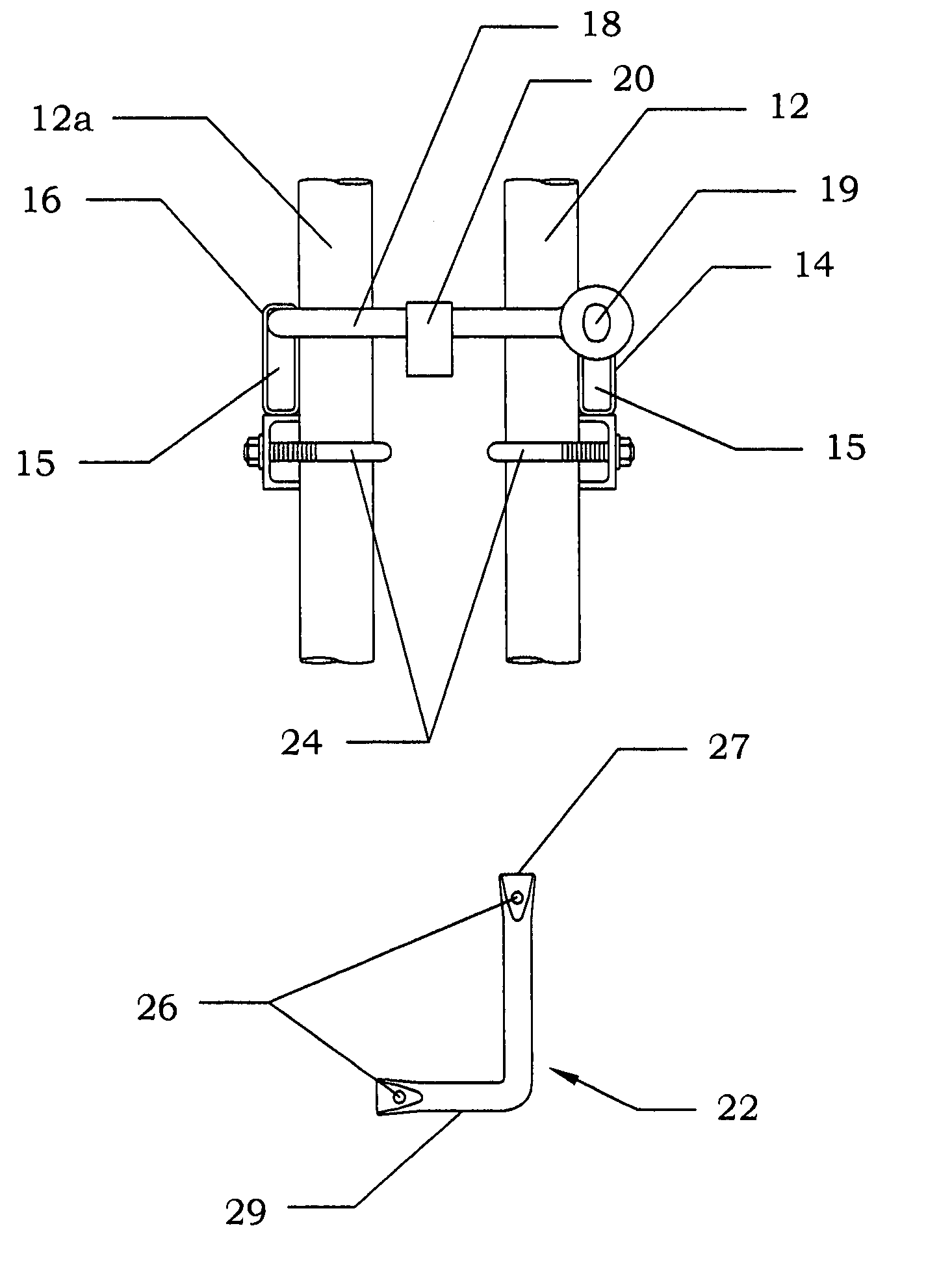
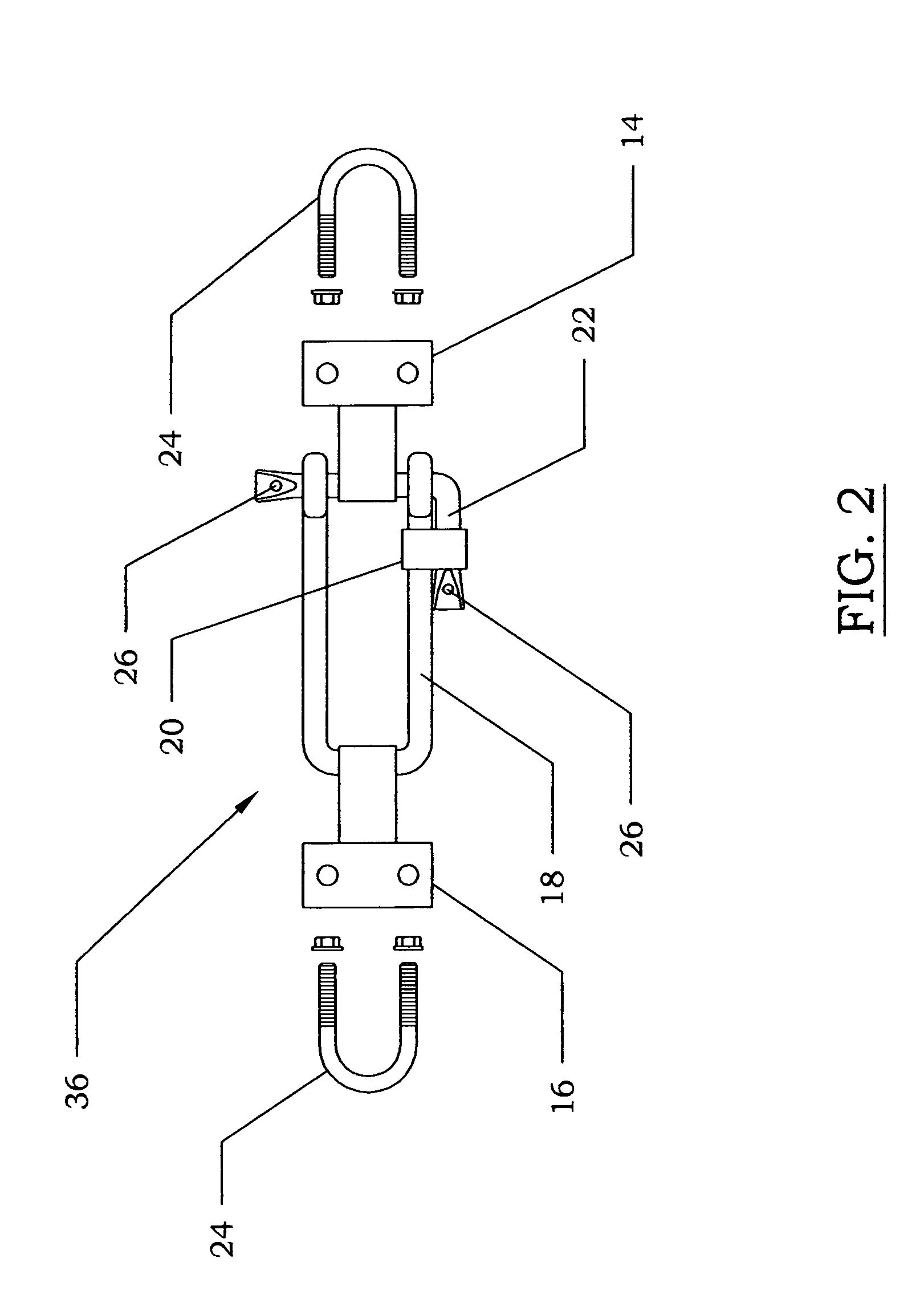
[0021]FIGS. 1 and 2 show the double gate latch embodiment 36. In this embodiment a locking hinge 14 is affixed to the outside of a gate frame 12, preferably with a U-bolt 24. An adjustable hinge 16 is affixed to the outside of a second gate frame 12a, preferably with a U-bolt 24. Both the locking hinge 14 and the adjustable hinge 16 contain openings 15 generally perpendicular to the plane of the gate. A U-shaped bar called a clevis 18 is inserted through the adjustable hinge 16. A top view of the clevis 18 is shown in FIG. 7. The clevis 18 can be made of any solid material, with the preferred material being stainless steel. The clevis 18 can be round or square in shape. In the preferred embodiment a square back clevis is used. The square back clevis 18 adds strength and durability to the invention for several reasons. Firstly, if force is applied to the clevis 18, the square back allows the force to be distributed along the entire width of the adjustable hinge 16, as opposed to only...
second embodiment
[0029]This second embodiment can be used with many different kinds of fences. Two examples include a chain link fence or a tubular steel gate. Different kinds of materials are used to construct different kinds of fences. Therefore, the mounting mechanism of the adjustable hinge 16 may change depending on what kind of material is used to construct the terminal post 10. For example, if the adjustable hinge 16 is attached to a wooden post, it may be attached with a nail or a bolt. However, if the adjustable hinge 16 is attaching to a steel post, it may be welded or secured with U-bolts.
[0030]The second embodiment does not have a locking hinge for the locking pin 22 to slide through; therefore, the locking pin 22 can be positioned through the gate frame 12 and under a sturdy structural member of the gate frame 12, such as a tubular bar. This takes weight off of the movable hinges of the gate by allowing the weight of the gate to be supported by the sturdy latch assembly. This may length...
fourth embodiment
[0032]FIG. 5 shows the invention called the roller gate latch 34. This latch system is for use with gates that slide shut, usually on rollers or any comparable mechanism. These gates operate in the same plane as the rest of the fence rather than having hinges that allow the gate to open at an angle to the fence line. The roller gate latch 34 comprises a gate receiver 28 that catches and guides the gate 12b into a latch gate cavity 31 as the gate 12b slides shut. The receiver 28 is comprised of an inside guide 28a with a flat end and a flared end, and an outside guide 28b with a flat end and a flared end. Each guide is positioned opposite from each other to define the latch cavity 31. Once in the latch cavity 31, a locking pin 22 is inserted through the gate receiver 28 to keep the gate closed. A lock is then inserted through the locking pin 22 and through a locking ring 30 attached to the gate receiver 28. The roller gate latch assembly body can be attached to any secure object thro...
PUM
 Abstract
Description
Claims
Application Information
 - R&D
- Intellectual Property
- Life Sciences
- Materials
- Tech Scout
- Unparalleled Data Quality
- Higher Quality Content
- 60% Fewer Hallucinations
Browse by: Latest US Patents, China's latest patents, Technical Efficacy Thesaurus, Application Domain, Technology Topic, Popular Technical Reports.
© 2025 PatSnap. All rights reserved.Legal|Privacy policy|Modern Slavery Act Transparency Statement|Sitemap|About US| Contact US: help@patsnap.com


