Clutch assembly

Inactive Publication Date: 2006-03-28
AISIN AW CO LTD +1
View PDF12 Cites 16 Cited by
  • Summary
  • Abstract
  • Description
  • Claims
  • Application Information

AI Technical Summary

Benefits of technology

[0010]It is an object of the present invention to provide a clutch assembly that allows a vehicle to take off without using a hydraulic power transmission such as a torque converter while having a simple structure in which neither oil chamber nor a clutch is disposed in a clutch case housed in a housing, thus improving reliability.
[0011]It is another object of the present invention to provide a clutch assembly that has a reduced radial size so as to improve ease of mounting the clutch assembly on the vehicle.
[0013]According to at least one example of the present invention, the vehicle can be started through transmission of an output of the engine to an input shaft of the automatic transmission by connecting / disconnecting the clutch without using the torque converter (T / C). This makes it possible to eliminate the slip between the input / output members as caused in the case where the T / C is employed, thus improving the transmission efficiency. In at least one example of the present invention, as an oil chamber is defined by fitting a piston of the clutch oil tightly with the housing, an oil leakage from the oil chamber to the housing can be prevented, further improving controllability of the clutch. The invention provides the clutch assembly having a simple structure by eliminating the clutch case for storing the clutch and the hydraulic actuator, as being separated from the housing, resulting in high reliability. As the damper device is aligned with the clutch with respect to the axial direction, a position of the damper spring can be freely determined in the radial direction of the damper device. This makes it possible to increase the degree of freedom in designing the damper device.
[0015]In the clutch assembly, according to at least another example of the invention, the clutch and the damper device are aligned in the axial direction. This makes it possible to prevent the clutch assembly from becoming unnecessarily large-sized in the radial direction in spite of the first and second springs disposed for providing damper function. The resultant mountability of the clutch assembly to the vehicle, thus, may be improved.

Problems solved by technology

The required size of the hydraulic power transmission, however, becomes relatively large.
This may interfere with reduction in weight and size of the vehicle.
As a lock-up clutch is employed to prevent a power loss that generally occurs during power transmission through the fluid, the structure of the hydraulic power transmission may become further complicated.
Even if the lock-up clutch is employed for the aforementioned reason, it cannot eliminate all the power loss.
The structure of the clutch assembly becomes complicated because of the needs for providing the thrust bearing and the oil passage in addition to the clutch case itself, thus degrading reliability of the clutch assembly.
Especially when two springs for the damper device are provided in the radial direction for improving the damper performance, the radial size of the clutch may further be increased, thus deteriorating ease of mounting the clutch assembly on the vehicle.

Method used


Image

  • Clutch assembly
  • Clutch assembly
  • Clutch assembly

Examples


Embodiment Construction

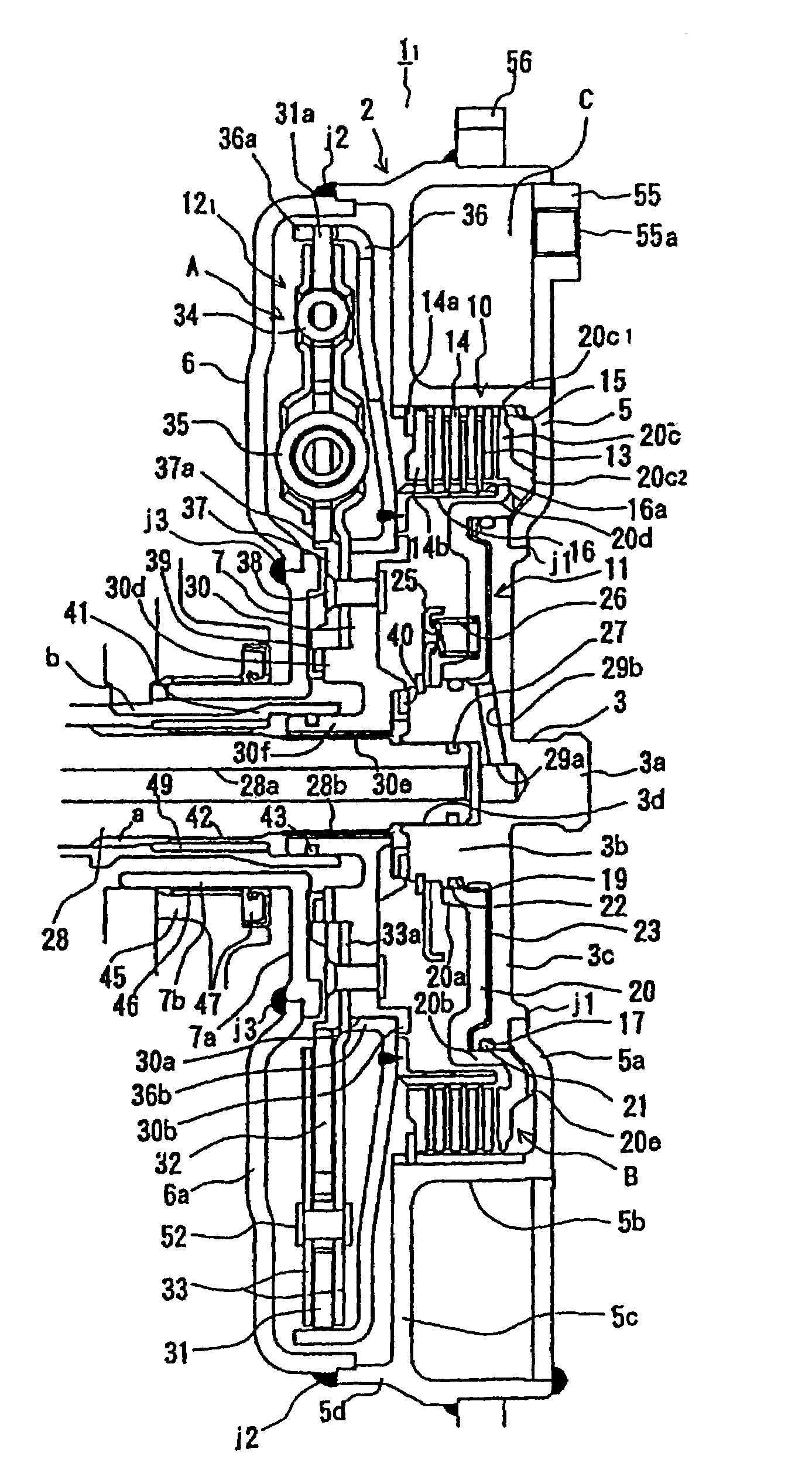
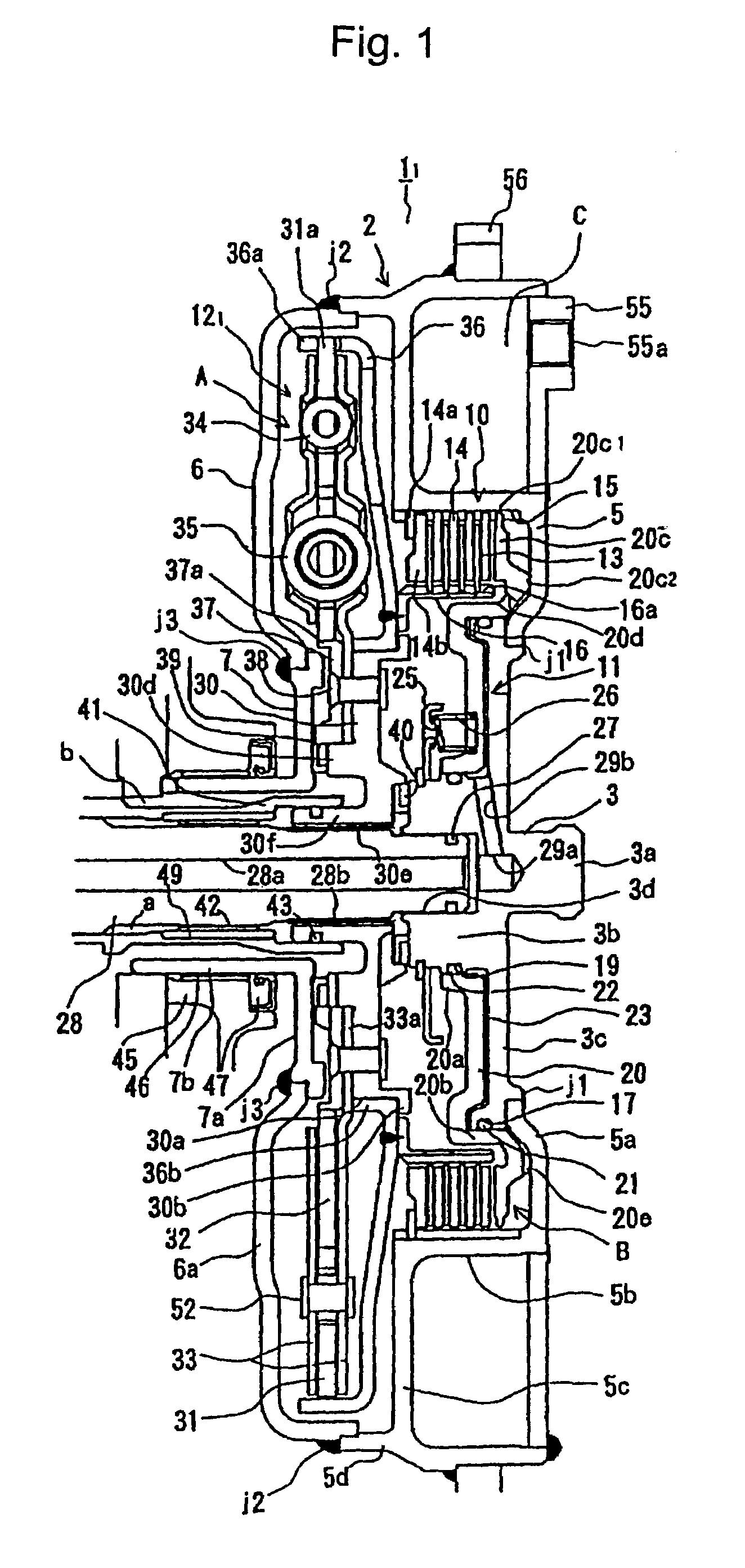
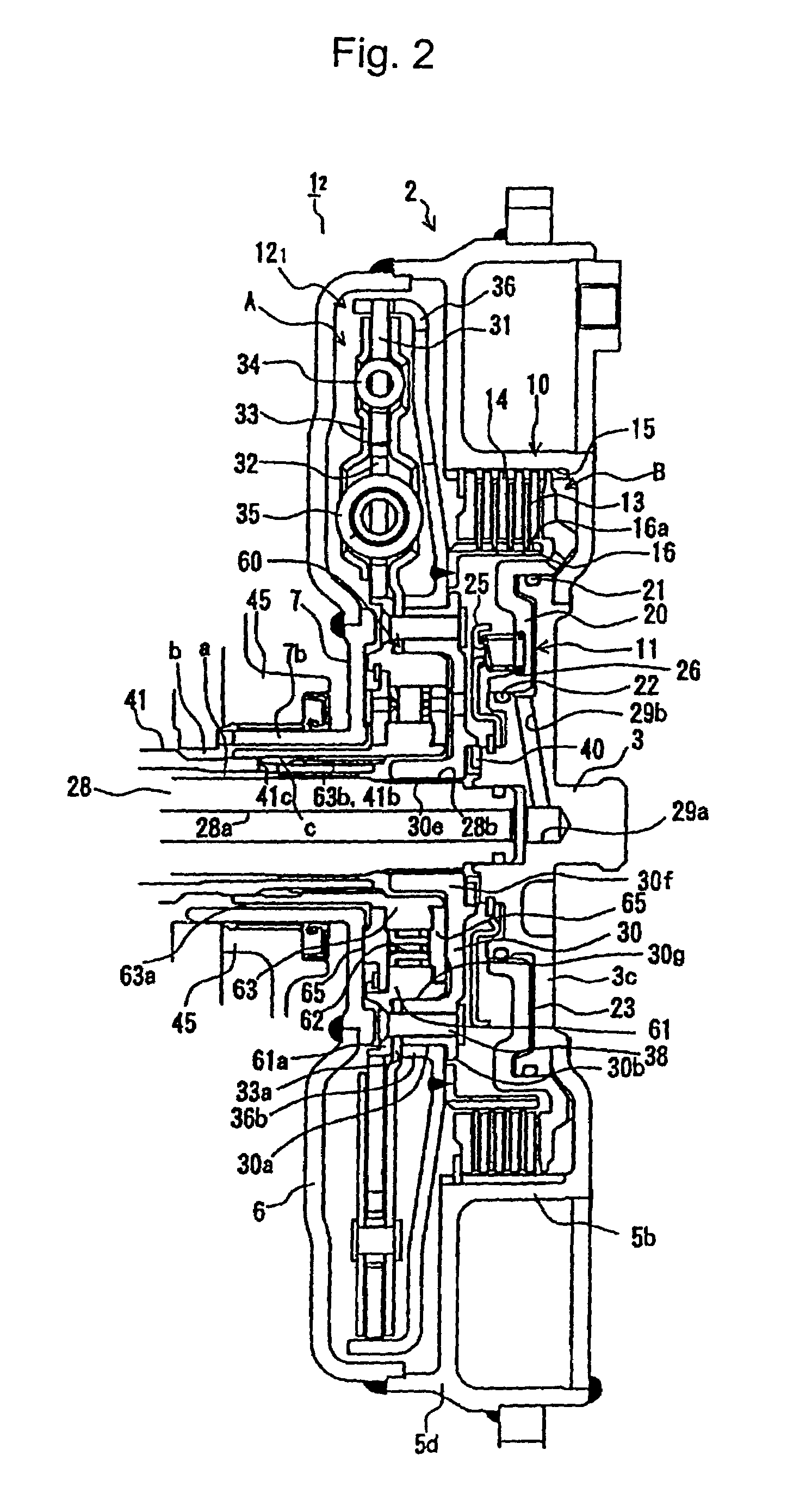
[0020]An embodiment of the present invention will be described referring to the drawings. FIG. 1 shows a clutch assembly with no one-way clutch. FIG. 2 shows a clutch assembly with a one-way clutch. FIG. 4 shows a clutch assembly as a modified embodiment in which an input or a drive member and an output or a driven member of the damper device are reversed. The clutch assembly is connected to an internal combustion engine such as a gasoline engine to the right of the drawings, and connected to an automatic transmission, for example, a CVT, an automatic transmission with multiple speeds (6 forward speeds and 1 reverse speed) and the like to the left of the drawings. The clutch assembly has a clutch controller that engages the clutch 10 (described later) to transmit outputs of the engine to the automatic transmission such that the vehicle takes off.

[0021]Referring to FIG. 1, a clutch assembly 11 includes a housing 2 that forms an outer frame of the clutch assembly 11. The housing 2 is ...


PUM


Abstract

A clutch assembly for starting a vehicle without using a torque converter has a simple structure yet providing high reliability. In the clutch assembly, a clutch and a damper device are housed in a housing connected to a crank shaft of an engine. A boss serving as an output member is connected to an input shaft of an automatic transmission. An output of the engine is connected / disconnected to / from the input shaft upon engagement / disengagement of the clutch. The clutch includes a friction member and a piston fit oil tightly with the housing so as to apply pressure to the friction member. One end of the damper device is connected to a clutch hub, and the other end is connected to the output member. The clutch and the damper device are aligned on the axis of the housing.

Description

FIELD OF THE INVENTION[0001]The present invention relates to a clutch assembly interposed between an engine and an automatic transmission of a vehicle, and more particularly, to a clutch assembly including a clutch and a damper device.BACKGROUND OF THE INVENTION[0002]Generally, a hydraulic power transmission, such as a torque converter and a fluid coupling, is employed as a clutch assembly of a vehicle. In the case where the hydraulic power transmission is employed in the vehicle having an internal combustion engine that keeps the drive source in an operating state, even if the vehicle is stopped, the fluid supplied from the hydraulic power transmission allows a relative rotation between an input shaft of the automatic transmission and an output shaft of the engine so as to keep the operation of the drive source. The fluid of the hydraulic power transmission, thus, allows the vehicle to have a smooth take-off and power of the engine is transmitted to the input shaft of the automatic...

Claims


Application Information

Patent Timeline
IPC IPC(8): F16D13/52B60K17/00F16D25/0638F16F15/134
CPCF16F15/13469F16D25/0638F16F15/134
Inventor HAYABUCHI, MASAHIROMAEDA, KOUJIYAMASHITA, TOMOHIROYAMAGUCHI, MASAHIROTAKESHITA, YOSHITOTANAKA, KATSUNORIFUKUDA, YUKIHIRO
Owner AISIN AW CO LTD
Why Eureka
Try Eureka