Magnetoresistive effect element, magnetic memory device and method of fabricating the same

element technology, applied in the direction of digital storage, semiconductor devices, instruments, etc., can solve the problems of insufficient output voltage for realizing a magnetic memory device having a higher density, insufficient value to achieve a further increase in storage speed or access speed, and insufficient value to achieve a further increase in the storing speed or access speed. , to achieve the effect of stable writing operation, convenient fabrication and efficient use of a stronger magnetic field

Inactive Publication Date: 2006-03-21
TDK CORPARATION
View PDF8 Cites 7 Cited by
  • Summary
  • Abstract
  • Description
  • Claims
  • Application Information

AI Technical Summary

Benefits of technology

[0011]The invention has been carried out in view of such a problem and it is a first object of the invention to provide a magnetic memory device capable of carrying out stable writing operation by efficiently utilizing a stronger magnetic field and a magnetoresistive effective element mounted thereon. It is a second object thereof to provide a magnetic memory device less effecting adverse influence on a contiguous memory cell and a magnetoresistive effective element mounted thereon. Further, it is a third object thereof to provide a method of easily fabricating such a magnetic memory device.

Problems solved by technology

Further, since all the information is lost when a power source is cut off, a nonvolatile memory needs to install as means for recording information other than the volatile memories and, for example, flash EEPROM, a magnetic hard disk device or the like is used therefor.
In the nonvolatile memories, high speed access poses an important problem in accordance with tendency of high speed information processing.
However, this value is insufficient for achieving a further increase in the storing speed or a further increase in the access speed.
However, even in the case of MRAM utilizing the TMR element showing the resistance change rate of about 40%, output voltage is about several tens mV and therefore, the output voltage is insufficient for realizing a magnetic memory device having a higher density.
Further, in the case of MRAM utilizing the TMR effect, information is stored to each memory cell by changing a magnetizing direction of a magnetic film by an induced magnetic field by current flowing in lead wires which are arranged orthogonal to each other, that is, a current magnetic field, however, the current magnetic field is an open (not confined to a specific region magnetically) magnetic field and therefore, not only the efficiency is low but also there is a concern of effecting adverse influence on a contiguous memory cell.
Further, in the case of achieving higher density formation of a magnetic memory device by highly integrating memory cells, miniaturization of a TMR element is indispensable, however, there is a concern of the following problem.

Method used


Image

  • Magnetoresistive effect element, magnetic memory device and method of fabricating the same
  • Magnetoresistive effect element, magnetic memory device and method of fabricating the same
  • Magnetoresistive effect element, magnetic memory device and method of fabricating the same

Examples


modified examples

[0156]Next, an explanation will be given of modified examples, according to the embodiment in reference to FIG. 26 as follows.

first modified example

[0157]The TMR element 22 according to the embodiment is constituted by a structure referred to as the coercive force difference type having the first magnetic layer 2 having the coercive force larger than that of the second magnetic layer 8. In contrast thereto, a TMR element 22B shown in FIG. 26A shows a structure referred to as the exchange bias type for fixing the magnetizing direction of the first magnetic layer 2 by the exchange coupling.

[0158]Specifically, the TMR element 22B includes a nonmagnetic conductive layer 9, the second magnetic layer 8, the tunnel barrier layer 3, the first magnetic layer 2 and a third magnetic layer 15 in this order from the side of the annular magnetic layer 4. The third magnetic layer 15 is provided with antiferromagnetism, functions to fix the magnetizing direction of the first magnetizing layer 2 by exchange interactive operation with the first magnetic layer 2, and constituted by an antiferromagnetic material of, for example, a platinum mangane...

second modified example

[0160]FIG. 26B shows a constitution of a TMR element 22C in which a nonmagnetic conductive layer 35 and a fourth magnetic layer 18 are provided between the first magnetic layer 2 and the tunnel barrier layer 3 in the constitution of the TMR element 22 according to the embodiment.

[0161]Specifically, the TMR element 22C includes the nonmagnetic conductive layer 9, the second magnetic layer 8, the tunnel barrier layer 3, the fourth magnetic layer 18, the nonmagnetic conductive layer 35 and the first magnetic layer 2 in this order from the side of the annular magnetic layer 4. The fourth magnetic layer 18 forms an antiferromagnetic coupling with the first magnetic layer 2 via the nonmagnetic conductive layer 35 and the magnetizing directions of the first magnetic layer 2 and the fourth magnetic layer 18 are in parallel and opposite direction with each other. The fourth magnetic layer 18 is constituted by, for example, iron (Fe), NiFe, CoFe, NiFeCo or cobalt (Co) or the like.

[0162]Accord...


PUM


Abstract

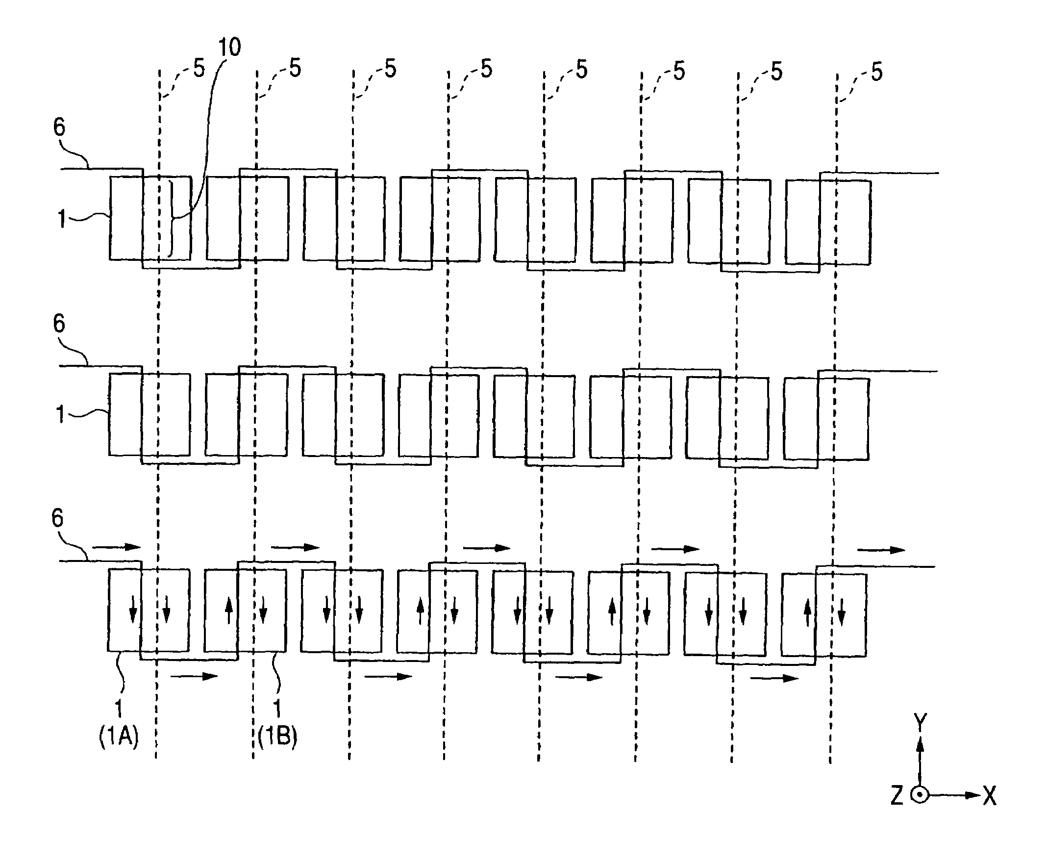
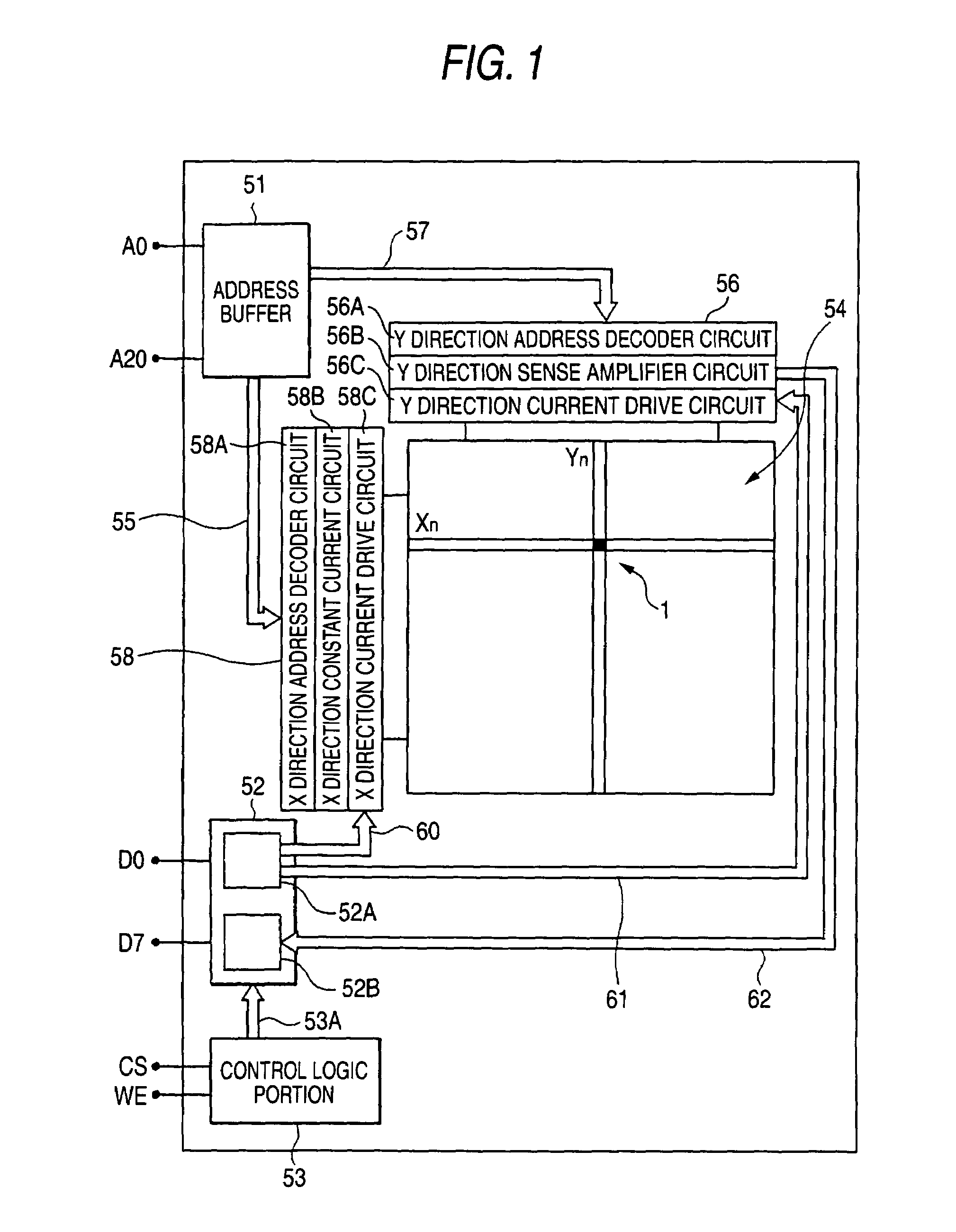
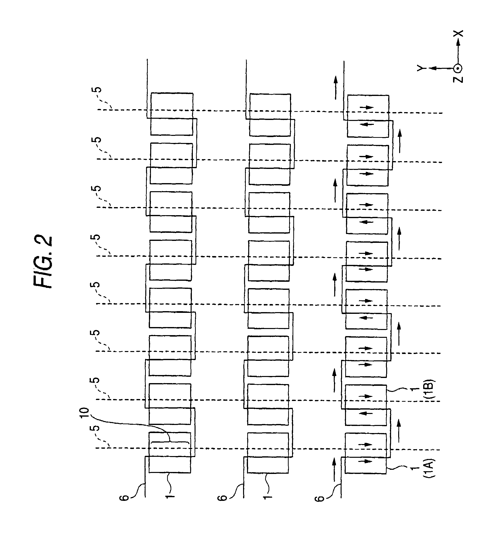
A magnetoresistive effect element includes a laminated body including a magnetosensitive layer a magnetizing direction of which is changed by an external magnetic field and constituted such that a current is made to flow in a direction orthogonal to a laminated layer face thereof, and a annular magnetic layer arranged at a side of one face of the laminated body to constitute an axial direction by a direction along the laminated layer face and constituted to be penetrated by a plurality of lead wires and therefore, a closed magnetic path can be formed by making current flow to a plurality of lead wires and inversion of magnetization at the magnetosensitive layer can further efficiently be carried out.

Description

BACKGROUND OF THE INVENTION[0001]The present invention relates to a magnetoresistive effect element including a ferromagnetic substance a magnetizing direction of which is changed by an external magnetic field, a magnetic memory device for storing information by utilizing a change in the magnetizing direction, and a method of fabricating the same.[0002]Conventionally, as a general-purpose memory used in information processing apparatus of a computer, a communication apparatus and the like, a volatile memory such as DRAM, SRAM or the like is used. The volatile memories need to refresh by incessantly supplying current for holding memory. Further, since all the information is lost when a power source is cut off, a nonvolatile memory needs to install as means for recording information other than the volatile memories and, for example, flash EEPROM, a magnetic hard disk device or the like is used therefor.[0003]In the nonvolatile memories, high speed access poses an important problem in ...

Claims


Application Information

Patent Timeline
Patent Type & Authority Patents(United States)
IPC IPC(8): G11C11/00G11C11/15G11C11/16H01L21/8246H01L27/105H01L27/22H01L43/08
CPCH01L27/222G11C11/16H10B61/00
Inventor EZAKI, JOICHIROKOGA, KEIJIKAKINUMA, YUJI
Owner TDK CORPARATION
Why Eureka
Try Eureka