Eureka AIR delivers breakthrough ideas for toughest innovation challenges, trusted by R&D personnel around the world.

Positioning system, positioning server, base station and terminal location estimation method

a positioning system and terminal technology, applied in direction finders using radio waves, navigation instruments, instruments, etc., can solve the problems of difficult to accurately estimate the location of mobile terminals, difficult to meet the needs of positioning-specific systems, and difficult to meet the needs of mobile terminals. accurate estimation

Inactive Publication Date: 2006-03-14
NEC CORP
View PDF8 Cites 32 Cited by
  • Summary
  • Abstract
  • Description
  • Claims
  • Application Information

AI Technical Summary

Benefits of technology

[0016]An object of the present invention is to provide a positioning system, a positioning server, a base station and a terminal location estimation method capable of accurately estimating the location of a mobile terminal when providing the information services according to the location of the mobile terminal in a radio communication system.
[0037]In addition, as radio wave propagation characteristics are the same even if the transmitting point and receiving point are replaced, the results of having the radio wave propagation environment measured by the terminal based on the radio wave transmitted from each of the base stations and the results of having the radio wave propagation environment measured by each of the base stations based on the radio wave transmitted from the terminal are equal. Accordingly, it is possible to shorten the estimation time and suppress the impact of the terminal movement by having the radio wave propagation environment measured by each of the base stations based on the radio wave transmitted from the terminal and estimating the terminal location based on the measurement results.

Problems solved by technology

However, facilities for using the positioning-specific system will be required.
There is a problem, however, that an resolution of the estimated terminal location becomes rough in the case of a small number of base stations.
In addition, as the terminal measures the electric field strengths of received radio waves from a plurality of base stations, there is a possibility that the measurement may take time and the terminal may move during the measurement in the case where the terminal has only one apparatus for measuring the electric field strength.
Although the measurement time can be shortened if the terminal has a plurality of measuring apparatuses, there is a possibility that having the plurality of measuring apparatuses may have an impact on the size, cost and power consumption of the terminal.

Method used


Image

  • Positioning system, positioning server, base station and terminal location estimation method
  • Positioning system, positioning server, base station and terminal location estimation method
  • Positioning system, positioning server, base station and terminal location estimation method

Examples


Embodiment Construction

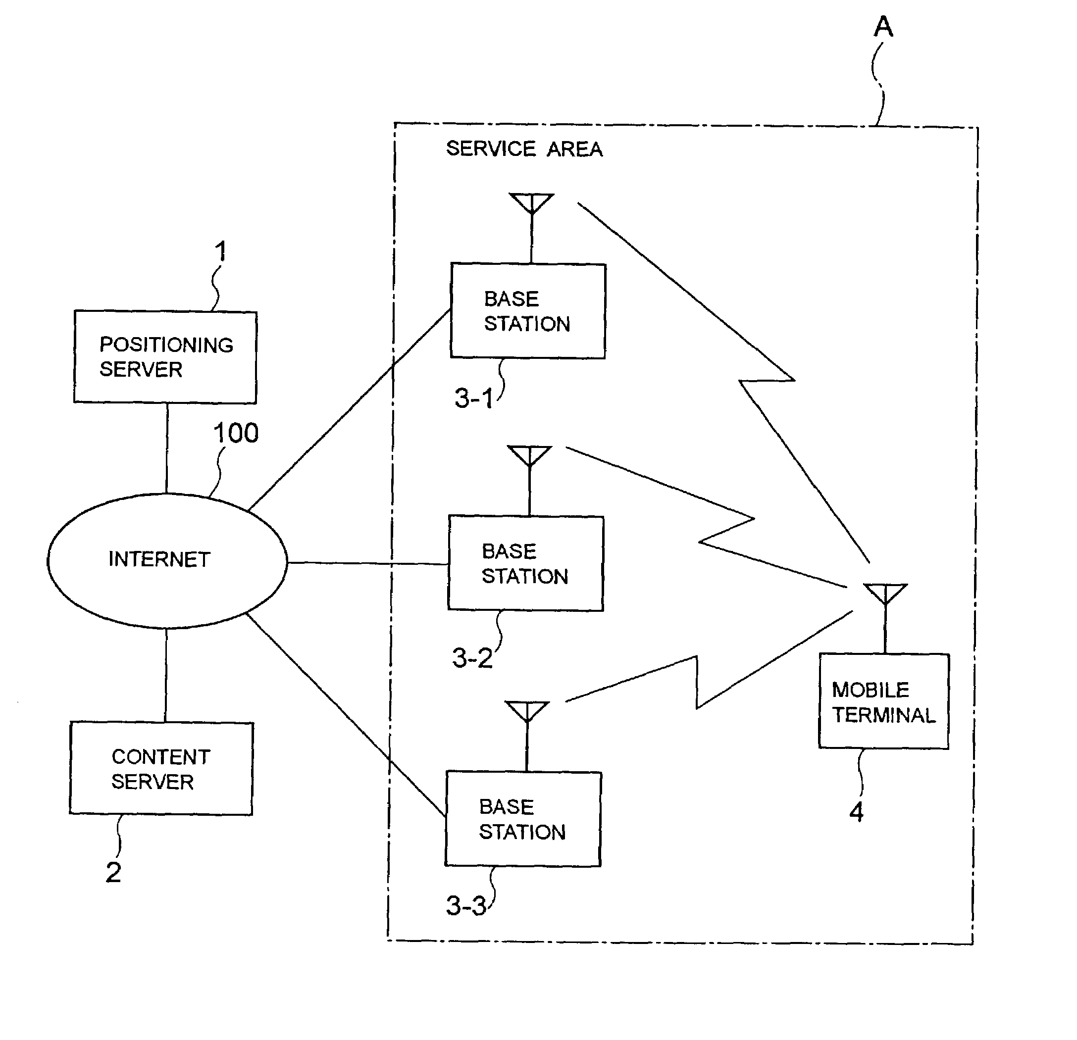
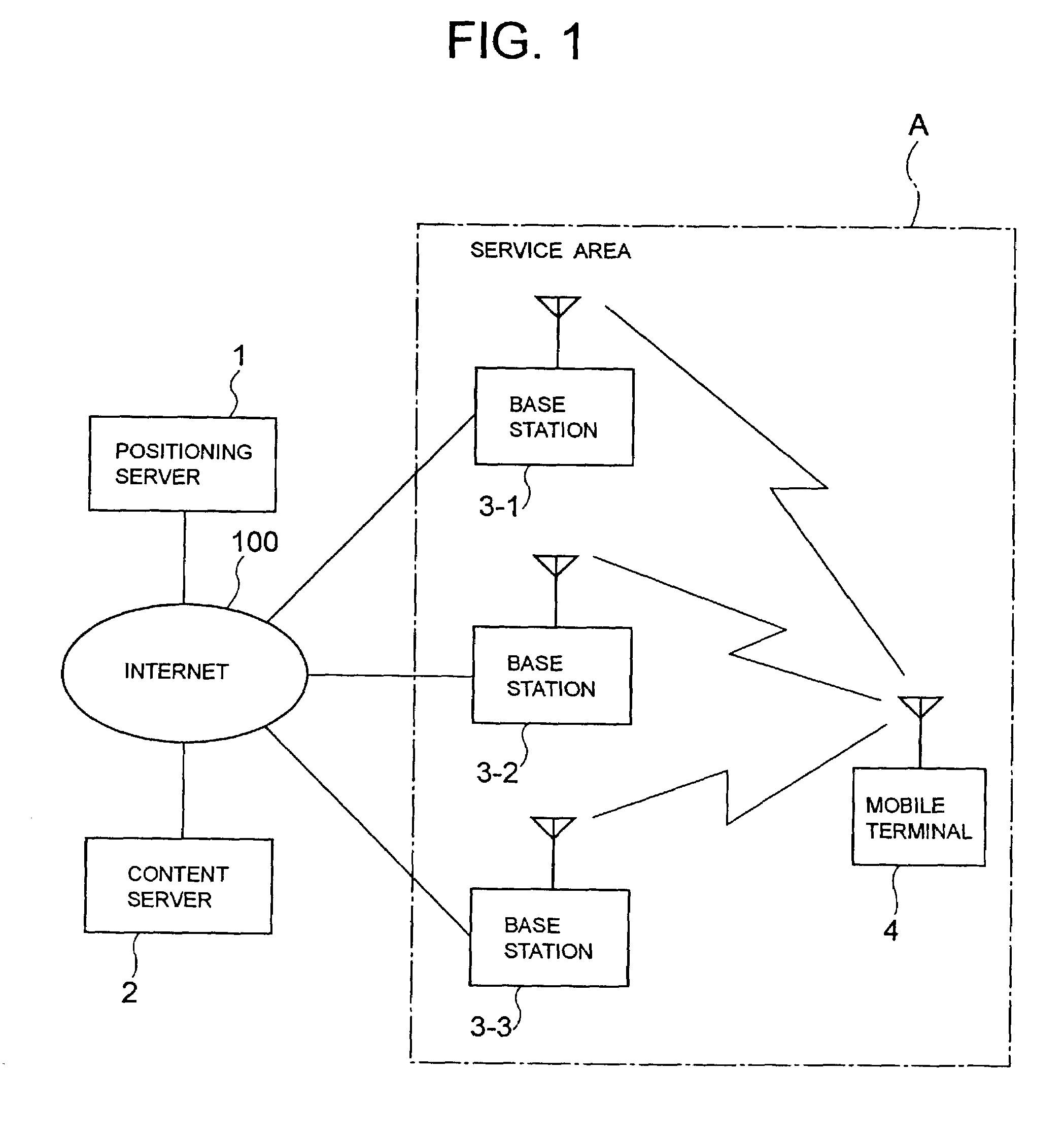
[0049]Next, an embodiment of the present invention will be described by referring to the drawings. FIG. 1 is a block diagram showing a configuration of a positioning system according to an embodiment of the present invention. In FIG. 1, reference symbol A represents a service area, reference numeral 1 denotes a positioning server, 2 denotes a content server, 3-1 to 3—3 denote base stations, 4 denotes a mobile terminal, and 100 denotes the Internet.

[0050]The positioning server 1, the content server 2 and the base stations 3-1 to 3—3 are connected to the Internet 100 respectively, and are capable of performing mutual communication. The mobile terminal 4 can obtain the information accumulated in the content server 2 via the base station 3-1, 3-2, 3—3.

[0051]The service area A is a range capable of radio communication by the base stations 3-1 to 3—3, and the terminal 4 performs the communication only in the service area A. That is, the base stations 3-1 to 3—3 provide the terminal 4 in t...


PUM


Abstract

To provide a terminal location estimation method capable of accurately estimating a location of a mobile terminal when providing information services according to the location of the terminal in a radio communication system. A positioning server sends a location measurement probe message to the mobile terminal in order to measure the location of the terminal. Each of base stations receives a response message broadcasted from the terminal, measures the reception level and delay spread and sends the measurement results to the positioning server. The positioning server has a radio wave propagation estimating portion and a database for storing estimation results thereof. The server estimates the location of the terminal by checking the measurement results of the base stations against the estimation results on radio wave propagation stored in the database.

Description

BACKGROUND OF THE INVENTION[0001]1. Field of the Invention[0002]The present invention relates to a positioning system, a positioning server, a base station and a terminal location estimation method, and in particular, to a method of easily and accurately detecting a location of a mobile terminal for utilizing a radio communication system.[0003]2. Description of the Prior Art[0004]In recent years, as represented by a portable telephone, services in keeping with a location at which a user exists are provided by utilizing a radio communication system, and these services are generally called location information services.[0005]An example of the location information services will be described by using FIGS. 9 and 10. FIG. 9 is a block diagram showing an example of a configuration of a positioning system in the past. In FIG. 9, reference numeral 21 denotes a positioning server, 200 denotes the Internet, 22 denotes a content server, 23-1 to 23-3 denote base stations, C-1 to C-3 denote cell...

Claims


Application Information

Patent Timeline
Patent Type & Authority Patents(United States)
IPC IPC(8): H04Q7/20G01S5/06H04W64/00
CPCG01S5/0036H04W64/00G01S5/0252G01S5/02521
Inventor OKANOUE, KAZUHIROFURUKAWA, HIROSHIYAMAZAKI, SHUNTARO
Owner NEC CORP
Why Eureka
Eureka Blog
Learn More