
Coated metal particles to enhance oil field shaped charge performance

a technology of coating metal particles and oil field, applied in the direction of explosive charges, weapons, ammunition projectiles, etc., can solve the problems of incoherent jets, and insufficient energy transfer to the liner for perforation

Inactive Publication Date: 2006-03-14
BAKER HUGHES INC
View PDF20 Cites 44 Cited by
  • Summary
  • Abstract
  • Description
  • Claims
  • Application Information

AI Technical Summary

Problems solved by technology

A drawback to increasing the quantity of explosive is that some of the energy of the detonation is expended in directions other than the direction in which the jet is expelled from the housing.
If the liner is collapsed at a speed (collapse speed) that exceeds the sound speed of the liner material the resulting jet will not be coherent.
Even if the liner geometry and sound speed of the shaped charge liner is optimized, the amount of energy which can be transferred to the liner for making the perforation is necessarily limited by the quantity of explosive.
However, solid liners suffer from the disadvantage of allowing “carrots” to form and become lodged in the resulting perforation—which reduces the hydrocarbon flow from the producing zone into the wellbore.
Each one of the aforementioned references relating to powdered metal liners suffer from the disadvantages of a limited shelf life, nonuniform density, and inconsistent performance results.
Shaped charge liners produced by traditional methods are subject to creep.
Slight expansion of the shaped charge liner reduces shaped charge effectiveness and repeatability.
A liner that is not homogeneous does not have a uniform density.
Therefore, the performance of the shaped charge liners cannot be accurately predicted which makes operational results that are difficult to reproduce.
A liner that has a non-uniform density will not form as coherent a jet as a liner having a uniform density.

Method used


Image

  • Coated metal particles to enhance oil field shaped charge performance
  • Coated metal particles to enhance oil field shaped charge performance
  • Coated metal particles to enhance oil field shaped charge performance

Examples


Embodiment Construction

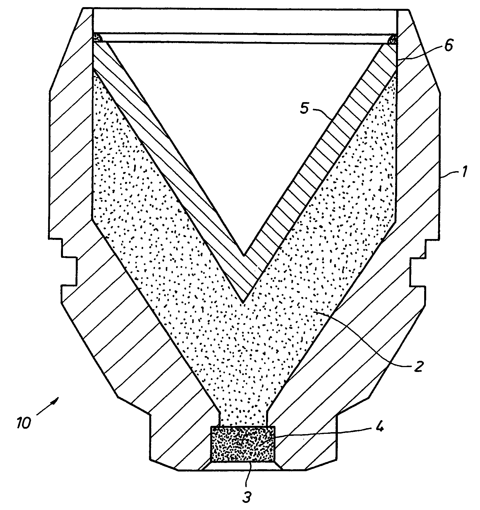
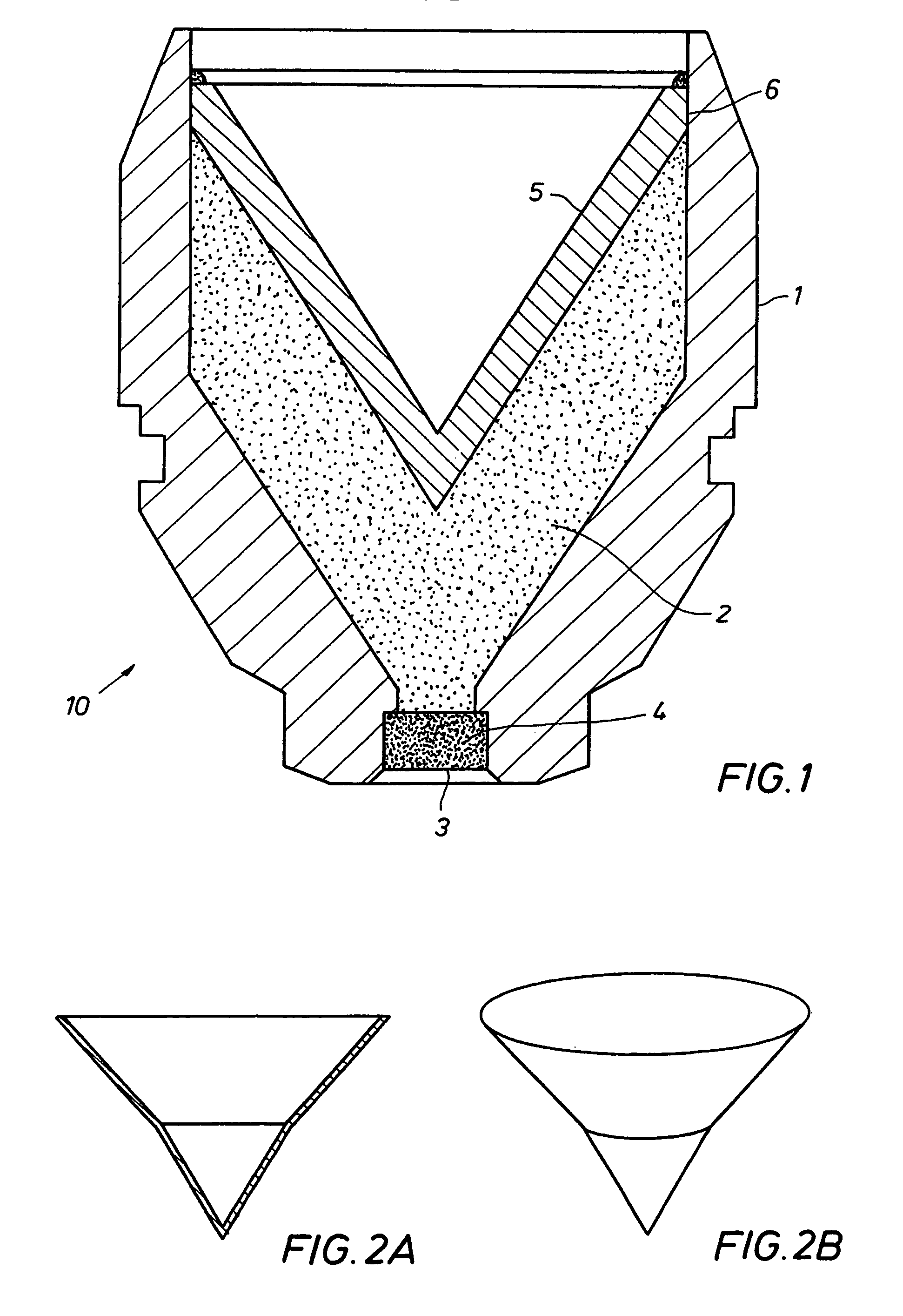
[0031]With reference to the drawings herein, a shaped charge 10 according to the invention is shown in FIG. 1. The shaped charge 10 typically includes a generally cylindrically shaped housing 1, which can be formed from steel, ceramic or other material known in the art. A quantity of high explosive powder, shown generally at 2, is inserted into the interior of the housing 1. The high explosive 2 can be of a composition known in the art. High explosives known in the art for use in shaped charges include compositions sold under trade designations HMX, HNS, RDX, PYX and TNAZ. A recess 4 formed at the bottom of the housing 1 can contain a booster explosive (not shown) such as pure RDX. The booster explosive, as is understood by those skilled in the art, provides efficient transfer to the high explosive 2 of a detonating signal provided by a detonating cord (not shown) which is typically placed in contact with the exterior of the recess 4. The recess 4 can be externally covered with a se...


PUM

PropertyMeasurementUnit
weightaaaaaaaaaa
chargeaaaaaaaaaa
velocityaaaaaaaaaa

Abstract

A liner for a shaped charge comprising powdered heavy metal tungsten coated with a metal binder coating compressively formed into a liner body. Each of the powdered heavy metal particles are substantially uniformly coated with metal binder coating. The preferred powdered heavy metal particles are comprised of tungsten. Optionally, the liner for a shaped charge includes a lubricant intermixed with the coated heavy metal particles. The metal binder coating is selected from the group consisting of copper, lead, nickel, tantalum, other malleable metals, and alloys thereof, and comprises from 40 percent to 3 percent by weight of the liner. The powdered heavy metal particles comprise from 60 percent to 97 percent by weight of the liner.

Description

RELATED APPLICATIONS[0001]This application claims priority from now abandoned U.S. Provisional Application No. 60 / 206,100, filed May 20, 2000, the full disclosure of which is hereby incorporated by reference herein.BACKGROUND OF THE INVENTION[0002]1. Field of the Invention[0003]The invention relates generally to the field of explosive shaped charges. More specifically, the present invention relates to a composition of matter for use as a liner in a shaped charge, particularly a shaped charge used for oil well perforating.[0004]2. Description of Related Art[0005]Shaped charges are used for the purpose, among others, of making hydraulic communication passages, called perforations, in wellbores drilled through earth formations so that predetermined zones of the earth formations can be hydraulically connected to the wellbore. Perforations are needed because wellbores are typically completed by coaxially inserting a pipe or casing into the wellbore, and the casing is retained in the well...

Claims


Application Information

Patent Timeline
Patent Type & Authority Patents(United States)
IPC IPC(8): F42B1/02F42B1/032
CPCF42B1/032
Inventor REESE, JAMES WARRENHETZ, AVIGDOR
Owner BAKER HUGHES INC
Learn More