
Lathe apparatus

a technology of lathes and cylinders, which is applied in the direction of attachable milling devices, wood turning machines, manufacturing tools, etc., can solve the problems of affecting the access of parts, affecting the work efficiency of the machine, and difficulty in accommodating a particularly long blank with the conventional lathe, so as to eliminate the shaft flex

Inactive Publication Date: 2006-03-14
WOODWORKERS SUPPLY
View PDF11 Cites 9 Cited by
  • Summary
  • Abstract
  • Description
  • Claims
  • Application Information

AI Technical Summary

Benefits of technology

[0003]Even further, conventional lathes tend to be boxy assemblies presenting monolithic rectangular headstocks and tailstocks which may hinder access to parts of the workpiece and / or may be uncomfortable to the operator, particularly if the operator leans on the headstock or tailstock during set-up or operation. Sharp corners may also cause minor but unpleasant injury. It would therefore be desirable to provide a more ergonomically shaped, smoothly contoured headstock and tailstock to minimize visual and physical obstructions and so as to be more comfortable in the event of operator contact. Ergonomically shaped and otherwise smoothly contoured assemblies are also highly desirable and attractive to consumers who, in general, find a modern, sleek and sophisticated appearance to be highly desirable.
[0006]Thus, it is a further object of the invention to provide a locking assembly for locking components, such as a tool rest, to a bedway in a manner that eliminates shaft-flex.
[0007]Accordingly, the tool rest provided in accordance with a presently preferred embodiment of the invention has a unique sliding piston locking system that eliminates shaft-flex, thereby ensuring a creep-free positive lockdown, even under the heavy impacts of large diameter outboard turning.

Problems solved by technology

While some lathes have beds that can be raised or lowered or moved towards and away from a headstock, in general, conventional lathes have limited versatility.
Indeed, it is difficult with conventional lathes to accommodate a particularly long blank, such as for a column, or a particularly wide blank, as may be provided when a bowl is to be turned.
Even further, conventional lathes tend to be boxy assemblies presenting monolithic rectangular headstocks and tailstocks which may hinder access to parts of the workpiece and / or may be uncomfortable to the operator, particularly if the operator leans on the headstock or tailstock during set-up or operation.
Sharp corners may also cause minor but unpleasant injury.
This can lead to bowing of the cam shaft and the potential for an incomplete clamping of the tool rest to the bedway.

Method used


Image

  • Lathe apparatus
  • Lathe apparatus
  • Lathe apparatus

Examples


Embodiment Construction

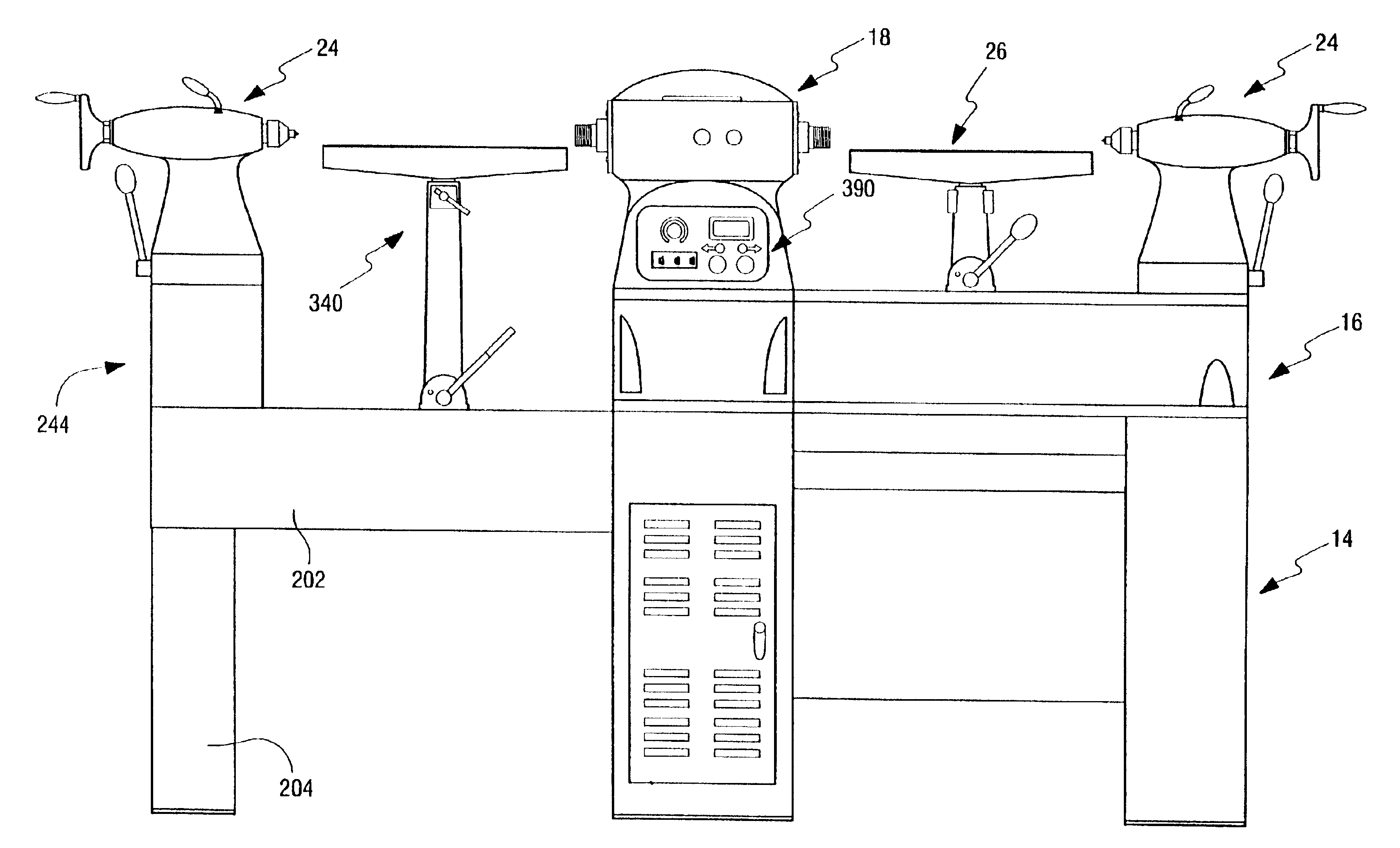
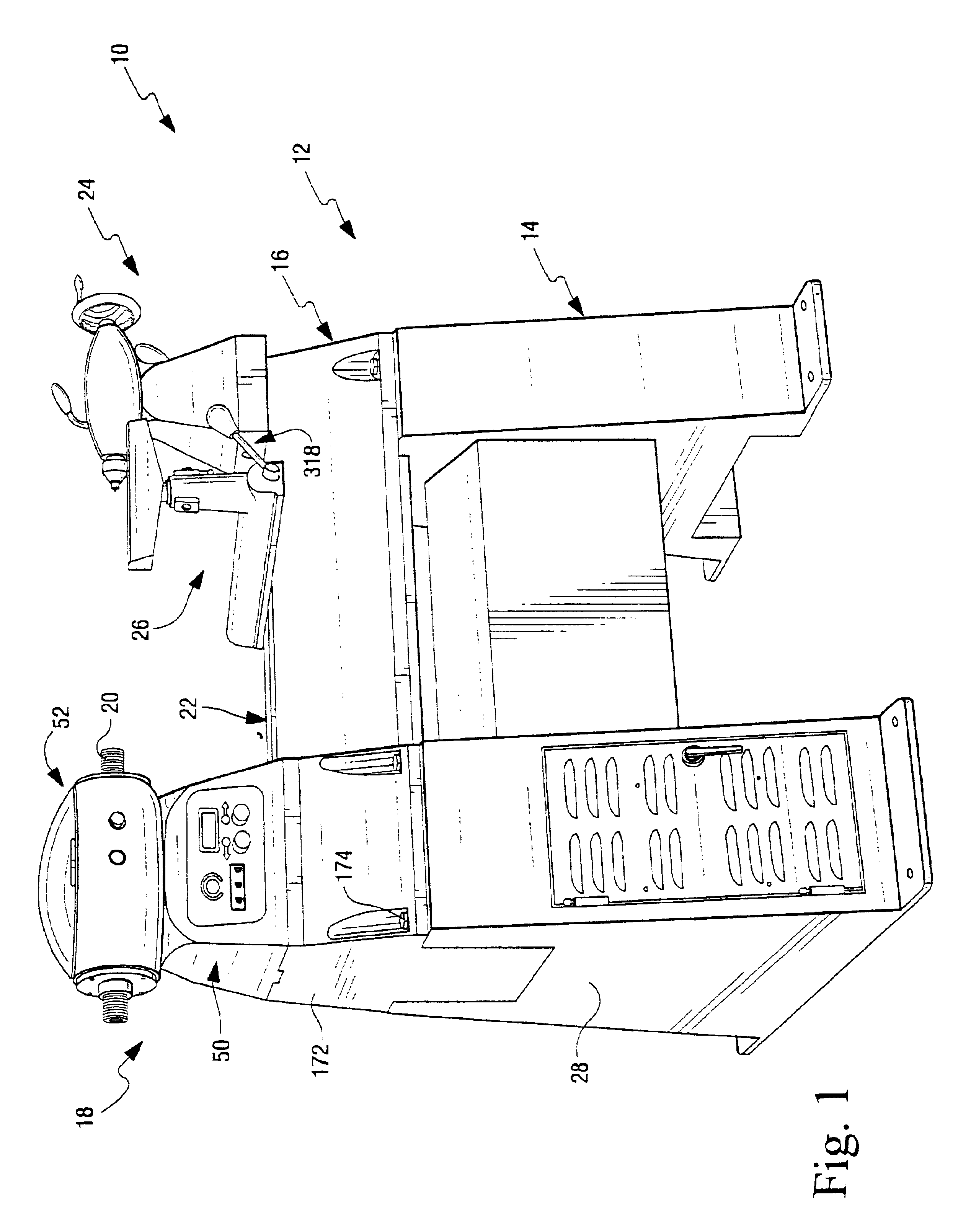
[0039]A basic lathe assembly embodying the invention is illustrated in FIGS. 1 and 25. As will be apparent below, a bed extension and / or outboard or inboard beds may be mounted to the basic lathe, as can inboard and outboard tool rests and inboard and outboard tailstocks as illustrated in FIGS. 26-29, to accommodate a wide variety of blank sizes and shapes including particularly long blanks such as for a decorative column or particularly wide workpieces such as a bowl.

[0040]The components of the basic lathe assembly, illustrated in FIGS. 1 and 25, will now be described in greater detail.

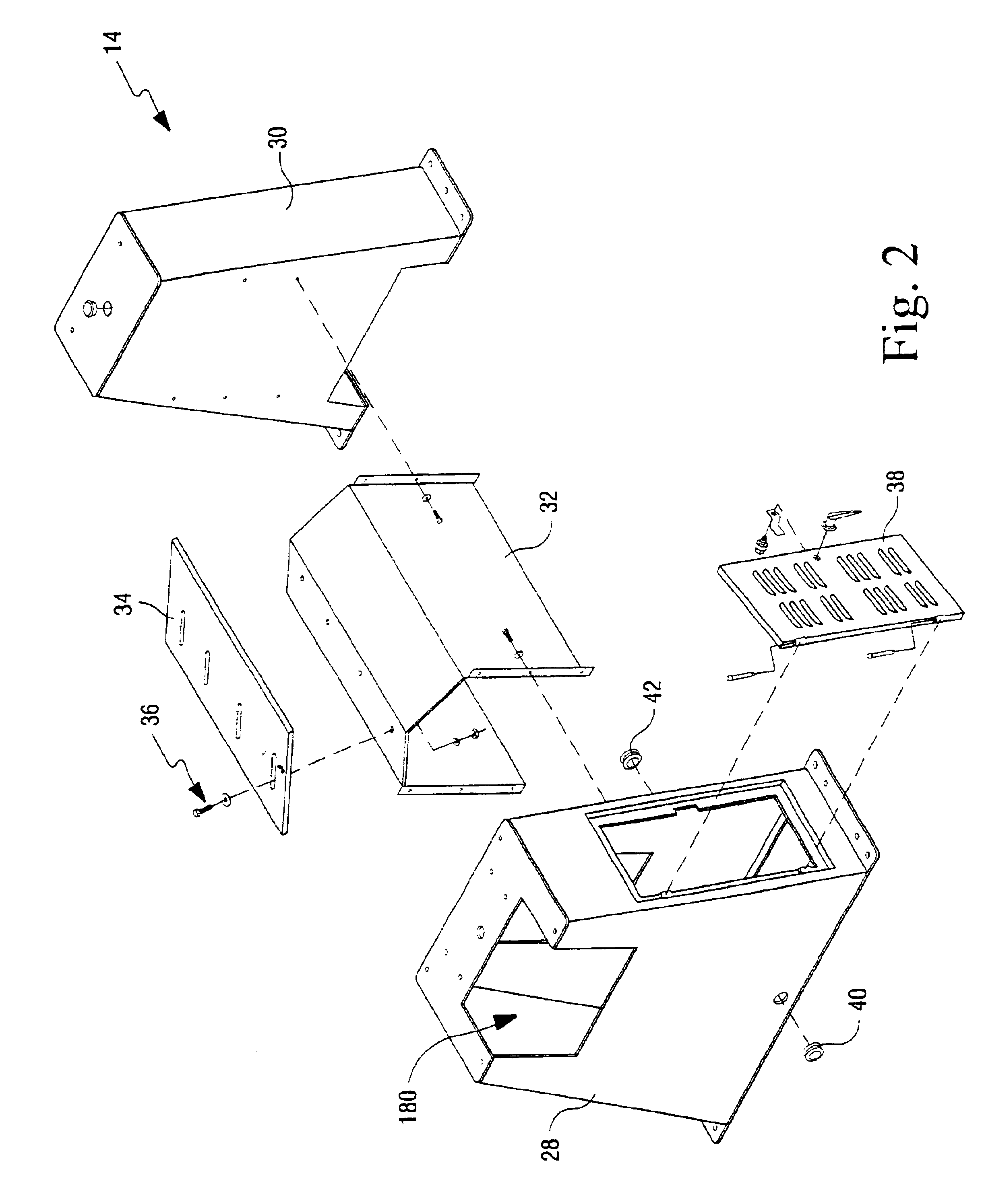
[0041]The basic lathe assembly 10 includes a base unit 12 that includes a lathe cabinet assembly 14 and a lathe bed 16. A headstock assembly 18 is mounted to one longitudinal end of the base unit 12 and includes a spindle 20 for engaging and rotating a workpiece (not shown). The lathe bed 16 includes a bedway 22 for selectively slidably receiving a tailstock assembly 24 and / or an inboard tool rest.

[0...


PUM

PropertyMeasurementUnit
Fractionaaaaaaaaaa
Angleaaaaaaaaaa
Poweraaaaaaaaaa

Abstract

The lathe provided in accordance with the invention is designed to address the needs of today's bowl and spindle turners. In an exemplary embodiment, the lathe of the invention comes equipped with a 2 hp DC BALDOR motor and a state-of-the-art 3 hp MINARIK pulse-width modulated (PWM) motor drive. It has a continuous power rating of 2 hp and an effective intermittent power rating of nearly 3 hp. The lathe has three speed ranges: 0 to 600 rpm for large bowl turning, 0 to 1200 rpm for standard bowl turning and 0 to 2000 for high-speed bowl turning and finishing. A number of accessory bed extensions are available along with an outboard tool rest and tailstock.

Description

BACKGROUND AND SUMMARY OF THE INVENTION[0001]Lathes are known for turning rotationally symmetrical elements such as bowls and spindles from a rectangular blank. Typically the workpiece is mounted between a headstock and a tailstock and rotated at high speed while a knife or knives are engaged with the rotating blank to cut and shave a desired profile into the blank. Lathes are typically used for turning wood blanks, but other materials such as metals and composite materials may be mounted and formed while turning on a lathe.[0002]While some lathes have beds that can be raised or lowered or moved towards and away from a headstock, in general, conventional lathes have limited versatility. Indeed, it is difficult with conventional lathes to accommodate a particularly long blank, such as for a column, or a particularly wide blank, as may be provided when a bowl is to be turned. In addition, it would be desirable to provide a lathe which allows the operator to selectively lock the workpi...

Claims


Application Information

Patent Timeline
IPC IPC(8): B23C7/02B23B17/00B23Q1/01B27C7/02B27C7/06
CPCB23Q1/01B27C7/02B27C7/06Y10T82/25Y10T82/2566Y10T82/2552Y10T82/24
Inventor WIRTH, JR., JOHNSANGER, JAY L.LATVEN, CHARLES H.FLEMING, KEVIN J.
Owner WOODWORKERS SUPPLY
Learn More