
Printing device

a printing device and roll-shaped technology, applied in the direction of typewriters, hammer-impression mechanisms, instruments, etc., can solve the problems of paper roll out, paper quantity is difficult to determine, printing cannot be completed, etc., and achieve the effect of high reliability

Inactive Publication Date: 2006-03-07
SEIKO EPSON CORP
View PDF30 Cites 28 Cited by
  • Summary
  • Abstract
  • Description
  • Claims
  • Application Information

AI Technical Summary

Benefits of technology

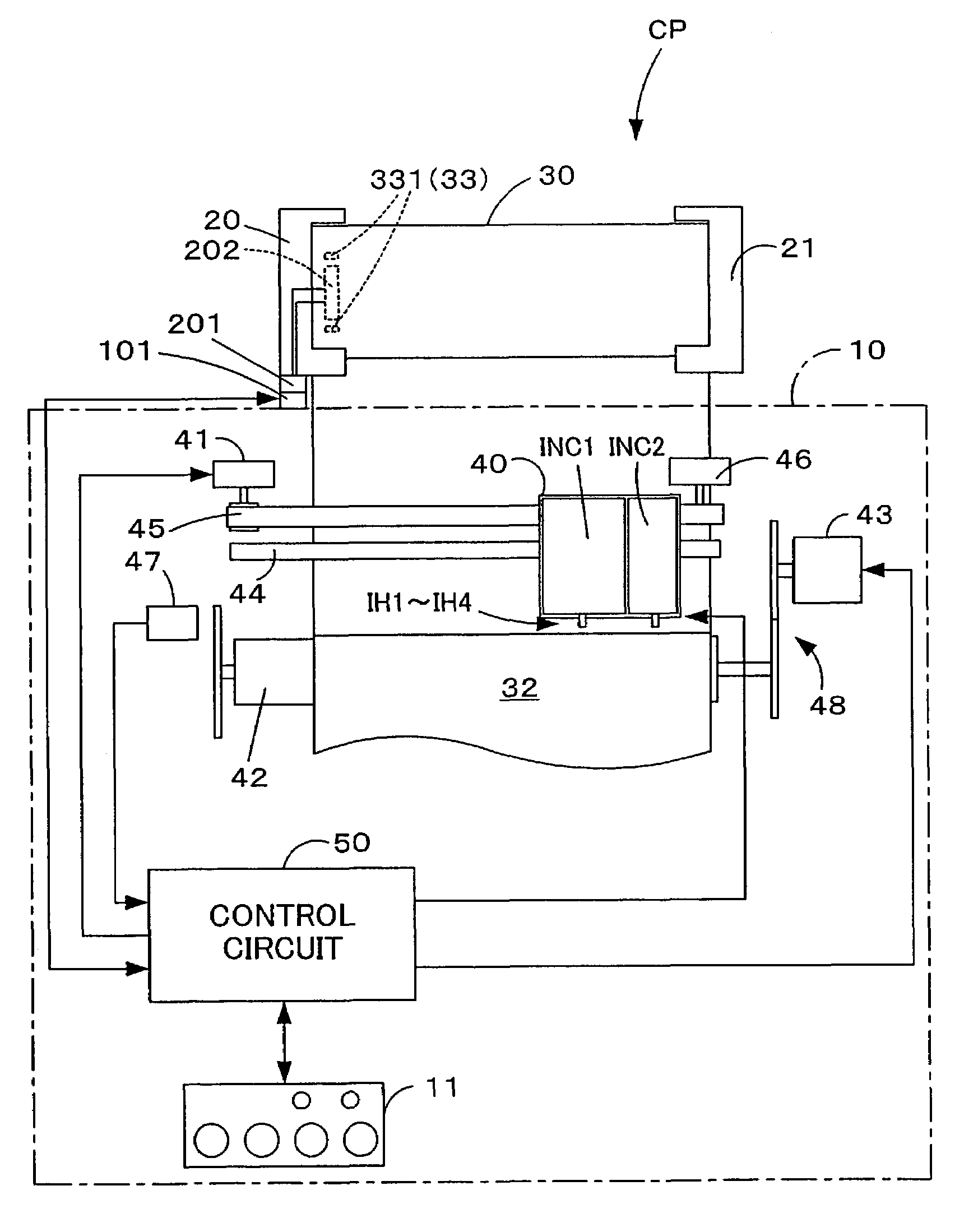
[0008]With the printing device in accordance with the first aspect of the present invention the paper feed quantity control of the roll paper for printing can be executed by using the information relating to the printing paper which is stored in the memory device. Therefore, the paper feed quantity control can be executed more appropriately.
[0025]In the roll paper member in accordance with the third aspect of the present invention, the transmission-reception device may be provided with an antenna for transmitting and receiving radio signals. In such a case, the paper-related information can be transmitted to and received from the printing device in a non-contact mode. Further, it is not necessary to consider a cover when arranging the antenna. Therefore, the degree of freedom in arranging the transmission-reception device is increased.

Problems solved by technology

By contrast with the cut paper for which the remaining quantity of paper can be easily visually determined, with roll paper, from which the paper is continuously fed to printing, the remaining quantity of paper is difficult to determine.
Accordingly, a problem associated with the roll paper is that when the remaining quantity of paper in the roll cannot be accurately controlled, the paper of the roll runs out before the printing processing of the entire page is completed and printing cannot be completed.
However, the problem is that when the remaining quantity of roll paper is stored in a device such as printer or personal computer, the remaining quantity of roll paper cannot be controlled unless a device storing the remaining quantity of roll paper is used.
The problem is, however, that installing a large-capacity memory in the printer increases the cost.
Another problem is that the information on the remaining quantity of roll paper is used only to control the remaining quantity of roll paper and the information on the remaining quantity of roll paper cannot be utilized effectively.

Method used


Image

  • Printing device
  • Printing device
  • Printing device

Examples


second embodiment

C. Example of the Configuration of the Roll Paper Printing System of the Second Embodiment

[0081]An example of the configuration of the roll paper printing system of the second embodiment will be described with reference to FIG. 8. FIG. 8 illustrates the external configuration of the roll paper printing system of the second aspect. Among the structural elements of the roll paper printing system of the second aspect, those structural elements that are identical to the structural elements of the roll paper printing system of the first embodiment are assigned with the same reference symbols and the explanation thereof is omitted.

[0082]In the roll paper printing system of the second aspect, a color printer CP2 is used as the printing device. In the color printer CP2, the roll paper member 30 is held with respect to the printer body with a roll paper support shaft 200 and a roll paper member holder 201 rotatably holding the roll paper support shaft 200.

[0083]A contact-type memory element ...

third embodiment

D. Example of the Configuration of the Roll Paper Printing System of the Third Embodiment

[0086]An example of the configuration of the roll paper printing system of the third embodiment will be described with reference to FIGS. 9 and 10. FIG. 9 illustrates the schematic configuration of the roll paper printing system of the third aspect. FIG. 10 is a side view of roll paper member used in the roll paper printing system of the third embodiment. Among the structural elements of the roll paper printing system of the third aspect, those structural elements that are identical to the structural elements of the roll paper printing system of the first embodiment are assigned with the same reference symbols and the explanation thereof is omitted.

[0087]In the first and second embodiments, the roll paper member 30 was used in which the roll paper 32 for printing was wound around the core 31. However, in the third embodiment, as shown in FIG. 9 and FIG. 10, a roll paper member 300 is used in whi...


PUM


Abstract

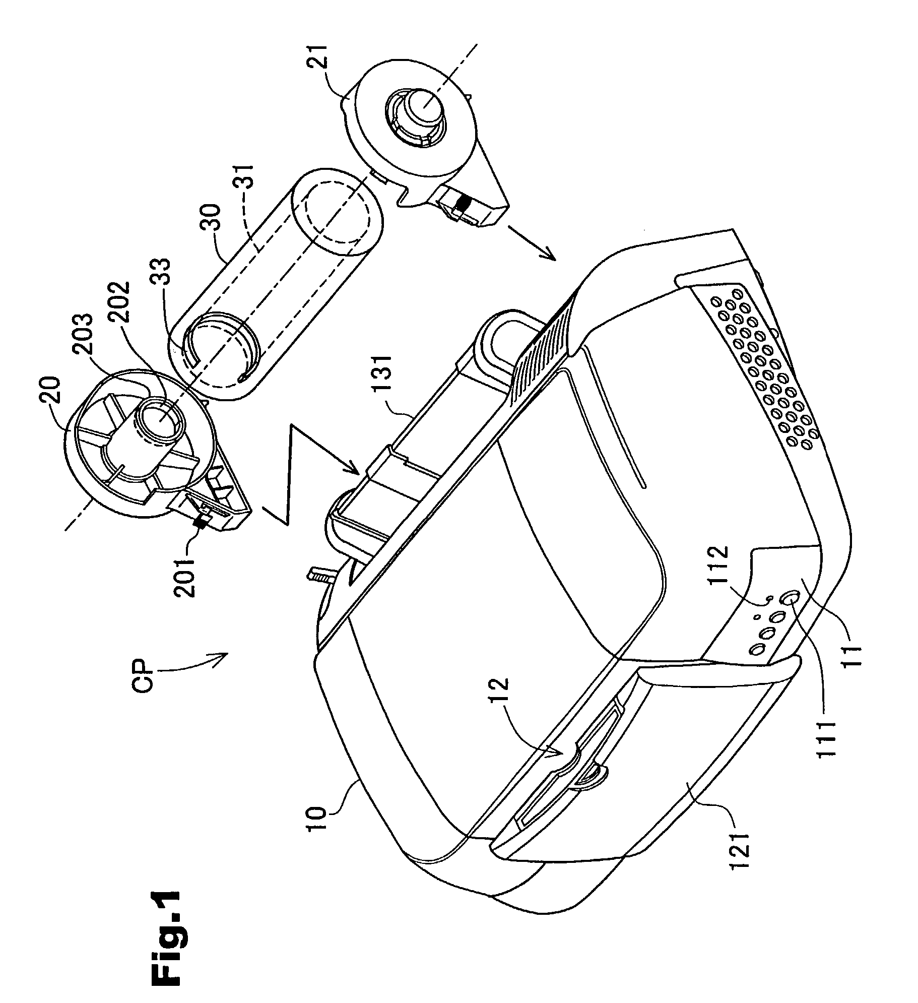
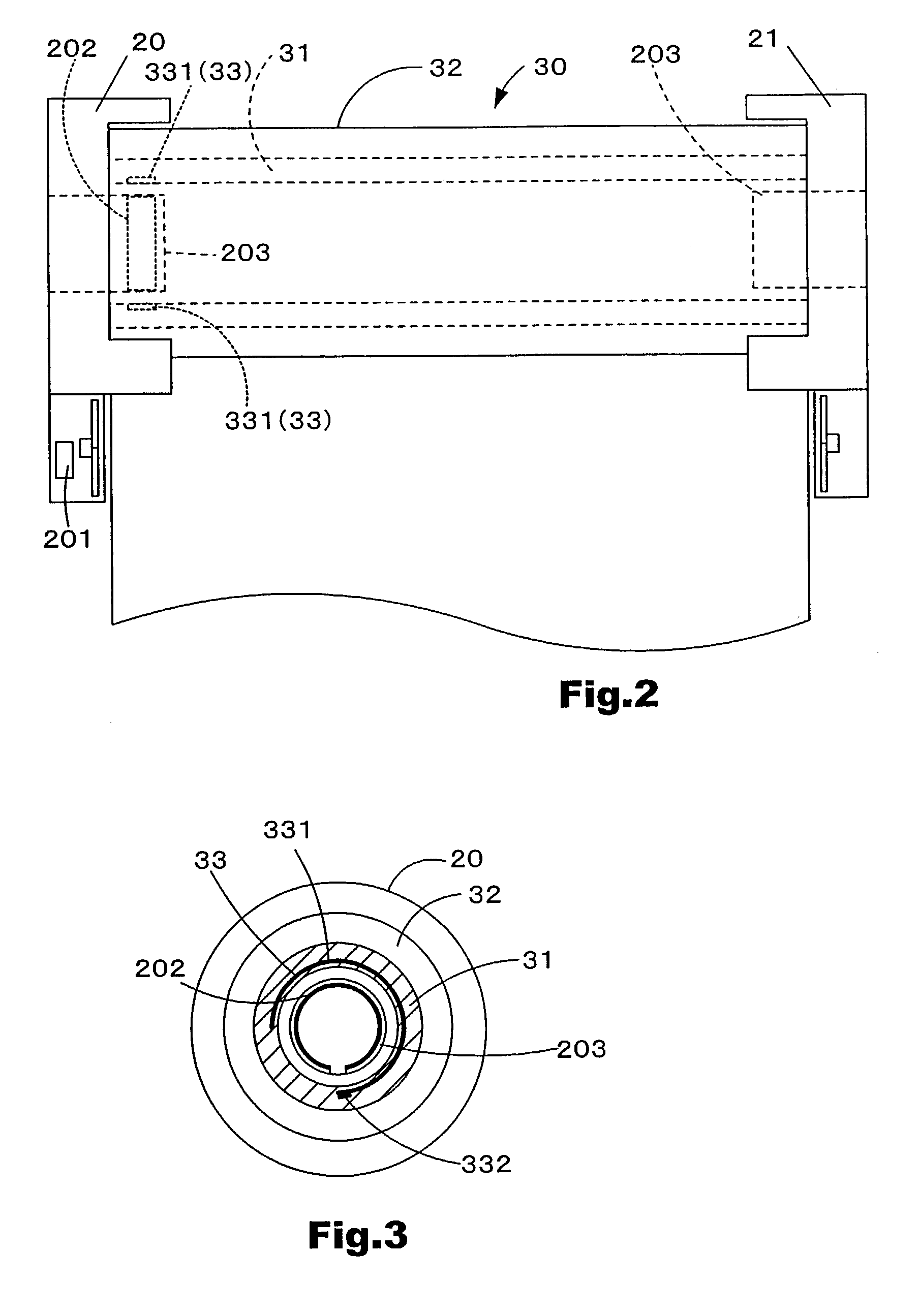
An IC memory module 33 for storing paper-related information is embedded in a core 31 of a roll paper member 30. A control circuit 50 accesses the IC memory module 33 embedded in the core 31 of roll paper member 30 via a transmission-reception antenna 202 at a timing, for example, when a power source is turned on, the roll paper member 30 is replaced, and power source is turned off, and acquires the paper-related information. The control circuit 50 controls the printing processing by taking account of the information acquired from the IC memory module 33.

Description

TECHNOLOGY FIELD[0001]The present invention relates to roll-shaped printing paper and a printing device for executing printing processing with respect to the roll-shaped printing paper.BACKGROUND ART[0002]A feed mode using cut paper that has been cut in advance to the prescribed size and a feed mode using roll paper obtained by winding paper for printing around a core are the main modes for feeding paper for printing in printing devices. The feed mode using roll paper is usually employed for feeding comparatively large paper requiring a large accommodation space, such as paper of A1 size, and the feed mode using cut paper is typically employed for feeding comparatively small paper, such as paper of A4 size.[0003]By contrast with the cut paper for which the remaining quantity of paper can be easily visually determined, with roll paper, from which the paper is continuously fed to printing, the remaining quantity of paper is difficult to determine. Accordingly, a problem associated wit...

Claims


Application Information

Patent Timeline
Patent Type & Authority Patents(United States)
IPC IPC(8): B41J21/17B41J11/42B41J17/00B41J33/14B41J11/00B41J15/02B41J15/04
CPCB41J11/009B41J15/04B41J15/02B41J11/42
Inventor NUNOKAWA, HIROKAZUKOSUGI, YASUHIKO
Owner SEIKO EPSON CORP
Learn More