
Door structure

a door structure and door frame technology, applied in the field of door structure, can solve the problems that conventionally assembled wooden doors are not amenable to powder coating, and achieve the effects of reducing gaseous emissions of volatile components, shortening the manufacturing time, and facilitating the design of panels

Inactive Publication Date: 2006-03-07
JELD-WEN
View PDF13 Cites 22 Cited by
  • Summary
  • Abstract
  • Description
  • Claims
  • Application Information

AI Technical Summary

Benefits of technology

The present invention provides a novel and useful panel door structure that has several technical effects. Firstly, the structure does not require the use of dowels or fasteners, which eliminates seams in the finished door structure. Secondly, the structure does not have stile and rail separation problems, which are common in conventional doors using mechanical fasteners. Thirdly, the structure allows hinge attachment when the panel door is constructed primarily of fiber material. Fourthly, the structure is economical to manufacture. Fifthly, the structure minimizes gaseous emissions of volatile components during the manufacture and finishing thereof. Lastly, the structure is versatile in allowing designs of panels to be quickly and easily determined. Additionally, the structure exhibits higher rigidity than doors of the prior art and may be manufactured using reduced tolerances.

Problems solved by technology

Unfortunately, conventionally assembled wooden doors are not amenable to powder coating since the interlocking elements and the fasteners employed in the construction of the door tend to separate upon the application of heat.

Method used


Image

  • Door structure
  • Door structure
  • Door structure

Examples


Embodiment Construction

[0042]Various aspects of the invention will evolve from the following detailed description of the preferred embodiments thereof which should be referenced to the prior delineated drawings.

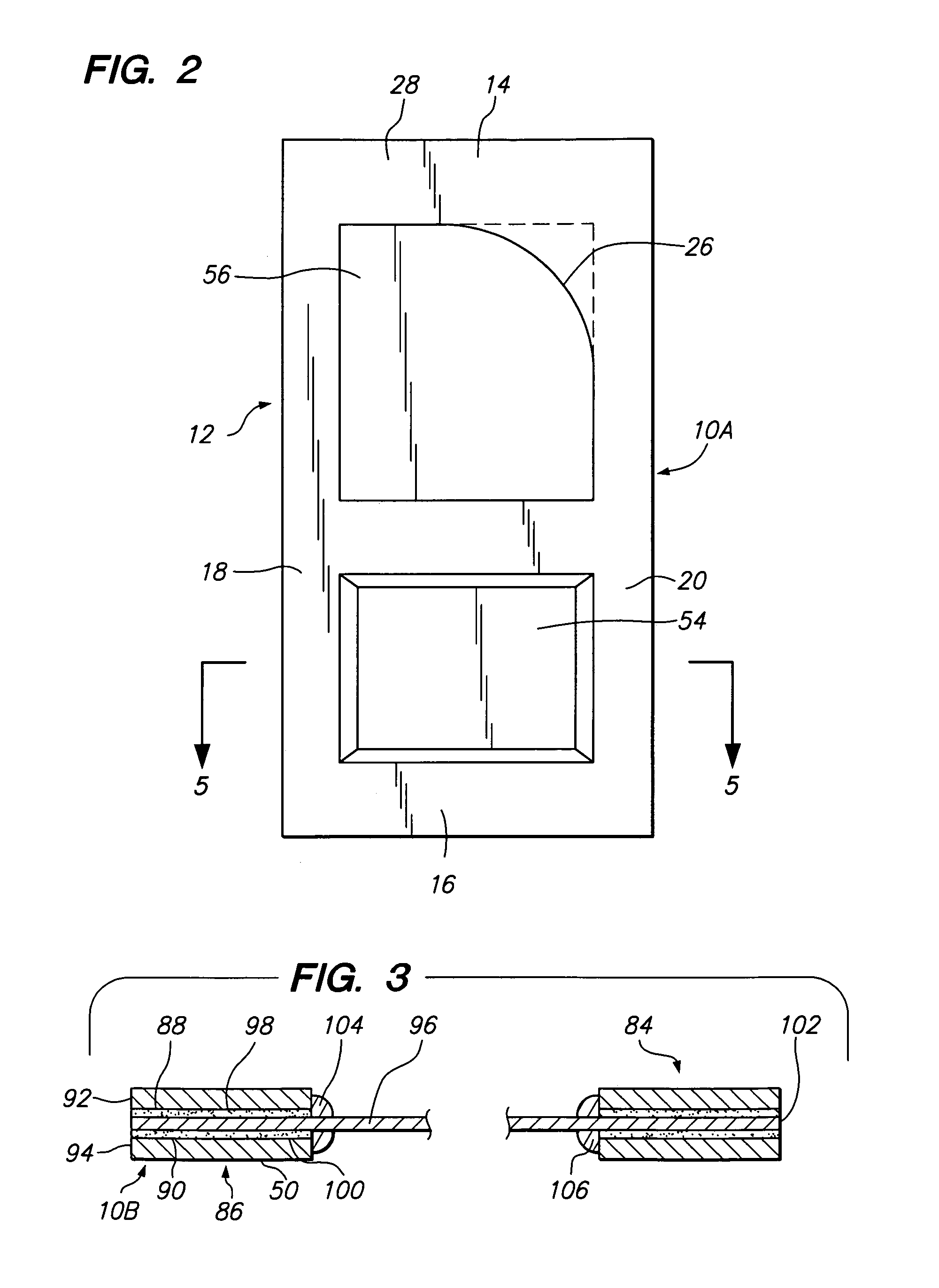
[0043]The preferred embodiment of the invention as a whole is shown in the drawings by reference character 10 followed by an upper case letter to denote variations thereof. With reference to FIGS. 1 and 2, embodiment 10A of the panel door structure of the present invention is depicted. Structure 10A includes as one of its elements a first skin unit 12. First skin unit 12 possesses a top portion 14, first side portion 18, and second side portion 20. Apertures 22 and 24 extend through first skin unit 12. It should be noted that aperture 24 possesses a curved edge 26. In addition, first skin unit 12 includes first surface 28 and an opposite second surface 30, FIG. 5.

[0044]A second skin unit 32 is also provided having a top portion 34, bottom portion 36, first side portion 38, and second side portion 4...


PUM


Abstract

A door structure utilizing a first skin having a surface. The first skin also includes an aperture through the same. A second skin is similarly constructed to the first skin such that the aperture of the second skin aligns at least partially with the aperture of the first skin. A panel is sandwiched between the first and second skin surfaces by first and second adhesive layers, respectively. The panel is positioned to at least partially occlude the apertures of the first and second skins.

Description

BACKGROUND OF THE INVENTION[0001]The present invention relates to a novel and useful panel door structure.[0002]Doors are typically assembled from multiple components, such as stiles, which extend vertically and one or more rails, which traverse a pair of stiles to form a frame. Panels are often placed within this frame by the use of interlocking mortises and tenons and muntins which interpose the stiles. Generally, mechanical fasteners are then employed to retain the plurality of elements into a unitary door. The door is then finished according to esthetic criteria and installed with hardware such as hinges, door knobs, latches, locks, and the like.[0003]Although doors have been traditionally constructed of wood, newer materials have proven satisfactory as a substitute for wood in this regard. For example, fibrous materials known as high-density fiber (HDF), medium density fiber (MDF), low-density fiber (LDF), and the like have been employed for this purpose.[0004]In addition, newe...

Claims


Application Information

Patent Timeline
Patent Type & Authority Patents(United States)
IPC IPC(8): E06B3/70E06B3/74E06B5/16
CPCE06B3/74E06B3/7001E06B2003/709E06B2003/7048E06B2003/7086E06B5/164
Inventor BALLANTYNE, MARK
Owner JELD-WEN
Learn More