
System and method for highly phased power regulation using adaptive compensation control

a power regulation system and adaptive compensation technology, applied in the direction of electric variable regulation, process and machine control, instruments, etc., can solve the problems of insufficient management and control, inability to efficiently accommodate power delivery of single operational mode converters, and inability to accurately manage traditional purely analog converter systems. achieve the effect of improving the power regulation system and improving the control featur

Inactive Publication Date: 2006-02-28
INFINEON TECH AUSTRIA AG
View PDF15 Cites 855 Cited by
  • Summary
  • Abstract
  • Description
  • Claims
  • Application Information

AI Technical Summary

Benefits of technology

[0012]The present invention overcomes the problems outlined above and provides an improved power regulation system. In particular, the present invention provides a power regulation system (power converter) with an improved control feature. More particularly, the system and methods of the present invention allow for independent control of one or more outputs from a single controlling unit.

Problems solved by technology

In general, conventional SPC systems adequately provide voltage regulation to a load, however, there are drawbacks.
Thus, a single operational mode converter typically cannot efficiently accommodate power delivery to complex or dynamic load requirements.
These complex systems require precise management and control which, in general, the traditional purely analog converter systems cannot adequately manage.
While transformers have shown some success in multi-output power conversion, these systems again typically require multiple controllers.
Current sensing of the load is difficult and typically requires bulky, lossy and inaccurate methods.
Voltage sensing has the disadvantage of lagging the current in the load.
Delays in both methods can lead to inadequate response of the SPC.

Method used


Image

  • System and method for highly phased power regulation using adaptive compensation control
  • System and method for highly phased power regulation using adaptive compensation control
  • System and method for highly phased power regulation using adaptive compensation control

Examples


Embodiment Construction

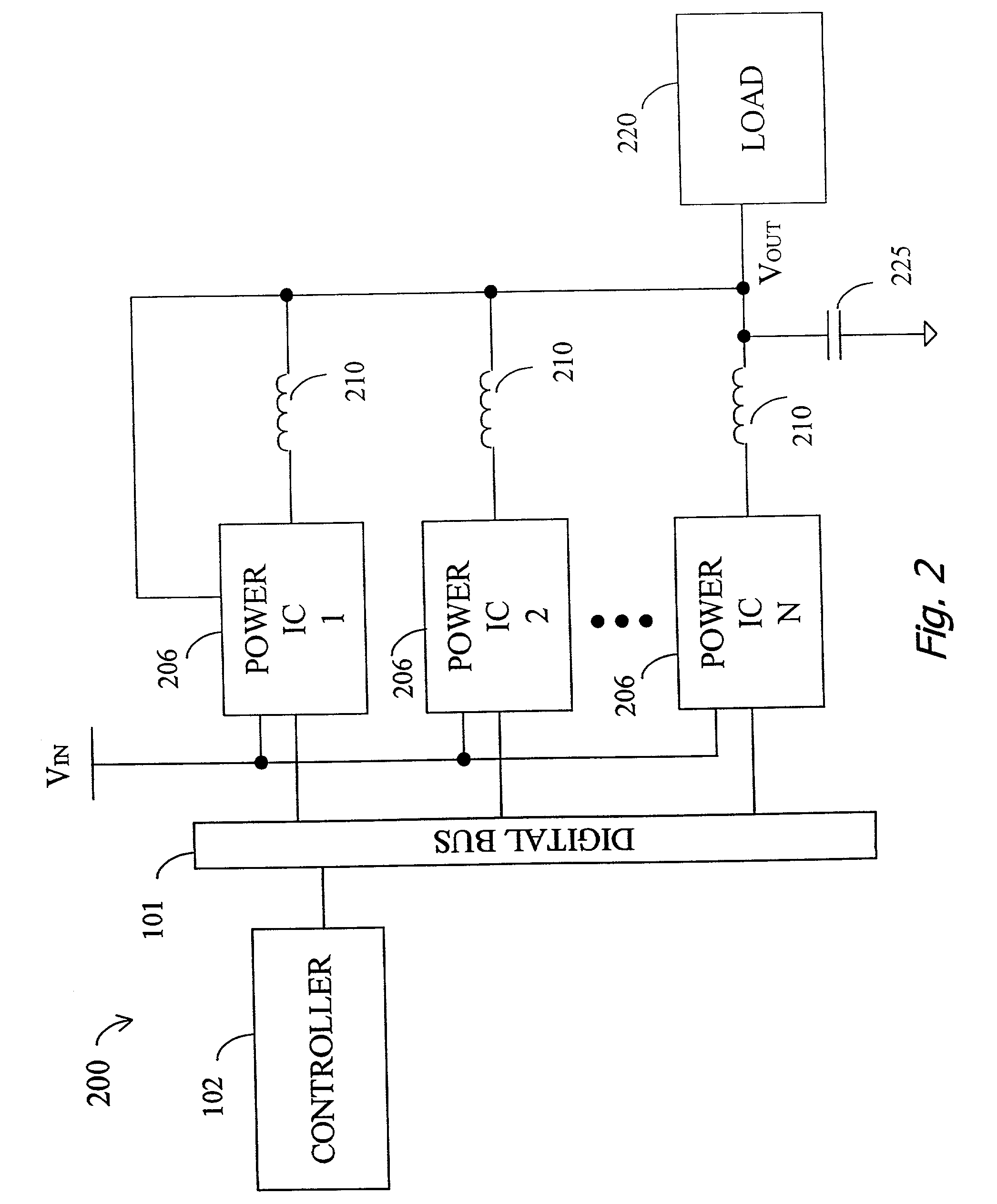
[0021]The present invention relates to an improved power regulation system or power conversion system. Although the power converter disclosed herein may be conveniently described with reference to a single or multiphase buck converter system, it should be appreciated and understood by one skilled in the art that any basic switching power converter (SPC) or regulator topology may be employed, e.g., buck, boost, buck-boost and flyback.

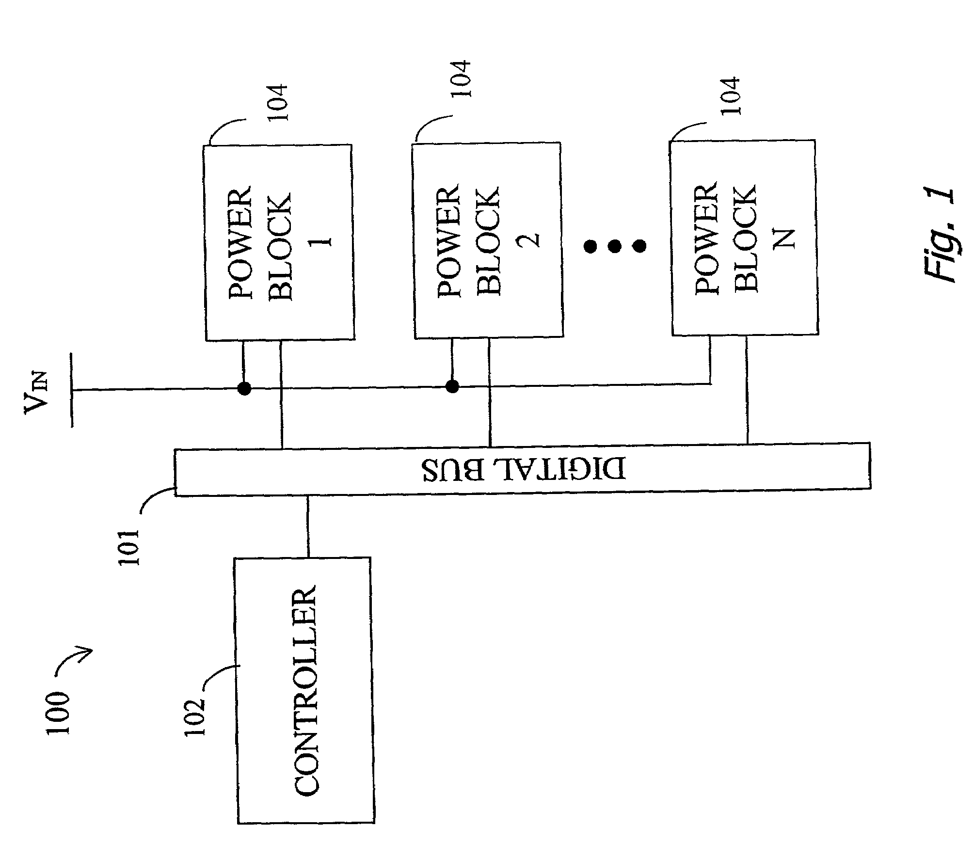
[0022]FIG. 1 illustrates, in simplified block format, a power regulation system 100 in accordance with one embodiment of the invention. System 100 includes a digital communication bus 101, a controller 102 and a plurality of power blocks 104. System 100 may be implemented in any basic SPC topology. In the preferred embodiment, system 100 receives an input source voltage (VIN) and converts the voltage to a desired number of outputs, with each output at a desired voltage, in a highly efficient and reliable manner.

[0023]System 100 is expandable to many phas...


PUM


Abstract

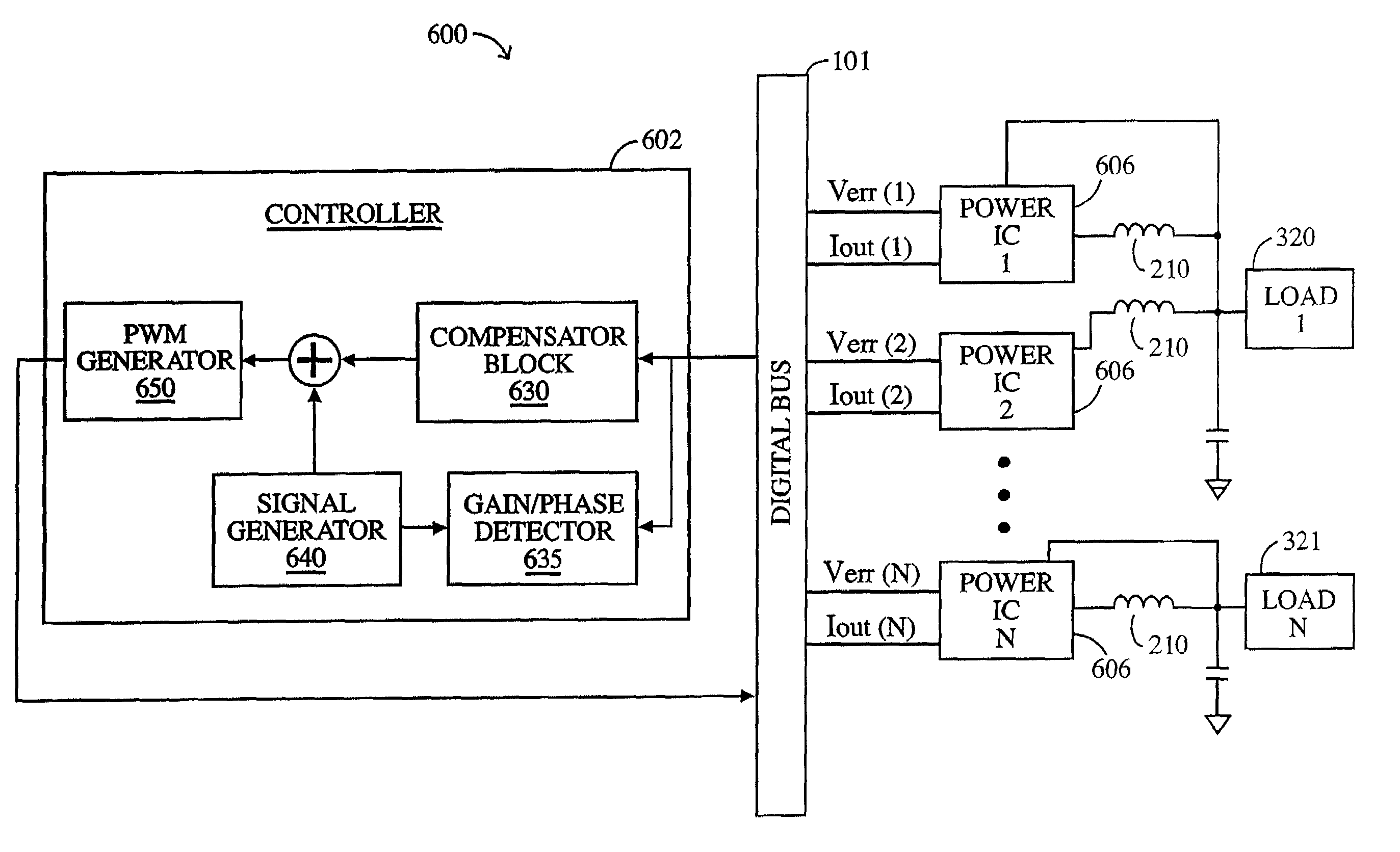
A highly phased power regulation (converter) system having an improved control feature is provided. A controller, such as a digital signal processor or microprocessor, receives digital information from a plurality of power conversion blocks and transmits control commands in response to the information. The controller is able to change the mode of operation of the system and / or re-phase the power blocks to accommodate a dynamic load requirement, occasions of high transient response or detection of a fault. A compensation block within the controller is used to regulate the output voltage and provide stability to the system. In one embodiment, the controller is implemented as a PID compensator controller. In another embodiment, a microprocessor is able to receive feedback on its own operation thus providing enabling the controller to anticipate and predict conditions by analyzing precursor data.

Description

CROSS REFERENCE TO RELATED APPLICATIONS[0001]This application is a continuation of U.S. Ser. No. 09 / 978,294, filed on Oct. 15, 2001 now abandoned, the disclosure of which is hereby incorporated by reference.[0002]This application includes subject matter that is related to and claims priority from U.S. Provisional Patent Application Ser. No. 60 / 240,337, filed on Oct. 13, 2000, entitled, “Adaptive Slope Compensation with DSP Control.”[0003]This application also includes subject matter that is related to and is a continuation-in-part of U.S. patent application Ser. No. 09 / 975,195, filed Oct. 10, 2001 now abandoned, entitled, “System and Method for Highly Phased Power Regulation” which claims priority from the following U.S. Provisional Patent Applications filed on Oct. 10, 2000: Ser. No. 60 / 238,993 entitled, “Multi Output Switching Power Converter with Optical I / O Microprocessor Control;” Ser. No. 60 / 239,049 entitled, “Multi Output Synchronous Power Conversion with DSP Control;” and Se...

Claims


Application Information

Patent Timeline
IPC IPC(8): G06F1/26H02J1/10H02M3/157H02M3/158H02M7/48H02M7/493
CPCH02J1/102H02M3/157H02M7/493H02M3/1584H02M2001/008H02M1/008
Inventor GOODFELLOW, RYANTRIVEDI, MALAYMORI, KEVIN
Owner INFINEON TECH AUSTRIA AG
Learn More