
Method and apparatus for the zonal transmission of data using building lighting fixtures

a technology of building lighting fixtures and data transmission methods, applied in the field of data transmission, can solve the problems of limited data transmission bandwidth, difficult to license, and difficult to coordinate, and achieve the effect of facilitating the operation of message paging

Inactive Publication Date: 2006-02-28
CONVERGENCE WIRELESS A CALIFORNIA CORP
View PDF13 Cites 146 Cited by
  • Summary
  • Abstract
  • Description
  • Claims
  • Application Information

AI Technical Summary

Benefits of technology

Enables accurate location tracking within buildings, reduces radio frequency congestion, and provides a cost-effective, easily installed wireless transmission system that supports secure and efficient data communication.

Problems solved by technology

However, the use of radio frequencies requires licensing and coordination for their use.
Given the overcrowded radio spectrum in some areas, said licensing may be nearly impossible.
In addition, while radio facilitates the transmission of data, in general that data transmission is limited in bandwidth and therefore limited in the speed of transmission.
Additionally, radio energy is hard to confine, and there it is not practical to limit data transmission to the confines of any one building or office within a building or office.
However, as infrared energy is not transparent to walls or other structures, the cost of installation of an independent building-wide infrared-based transmission system is extreme.
Each infrared transmitter will require lines for it's operating power and a data line for the data that is to be transmitted, thus requiring a supporting infrastructure that is both extensive and expensive.
In addition to wireless optical transmission as examined above, several examples exist of using modulated light in conjunction with optical fibers for the transmission of data, but these do not lend themselves to application to devices that are portable or mobile within buildings or offices.

Method used


Image

  • Method and apparatus for the zonal transmission of data using building lighting fixtures
  • Method and apparatus for the zonal transmission of data using building lighting fixtures
  • Method and apparatus for the zonal transmission of data using building lighting fixtures

Examples


embodiments

[0070]Main Embodiments

[0071]Note that part names as used herein are descriptive only, and should not be taken as limiting their function or purpose. It is important to note that functional blocks in the figures are shown for purposes of discussion only, and nothing therein should be construed to imply their necessary configuration or even presence for my invention to work. In addition, similar embodiments based on infrared, visible, or ultra-violet optical communications, or a combination thereof, or a mix of one spectrum for transmission and a different spectrum for reception, are anticipated by this invention.

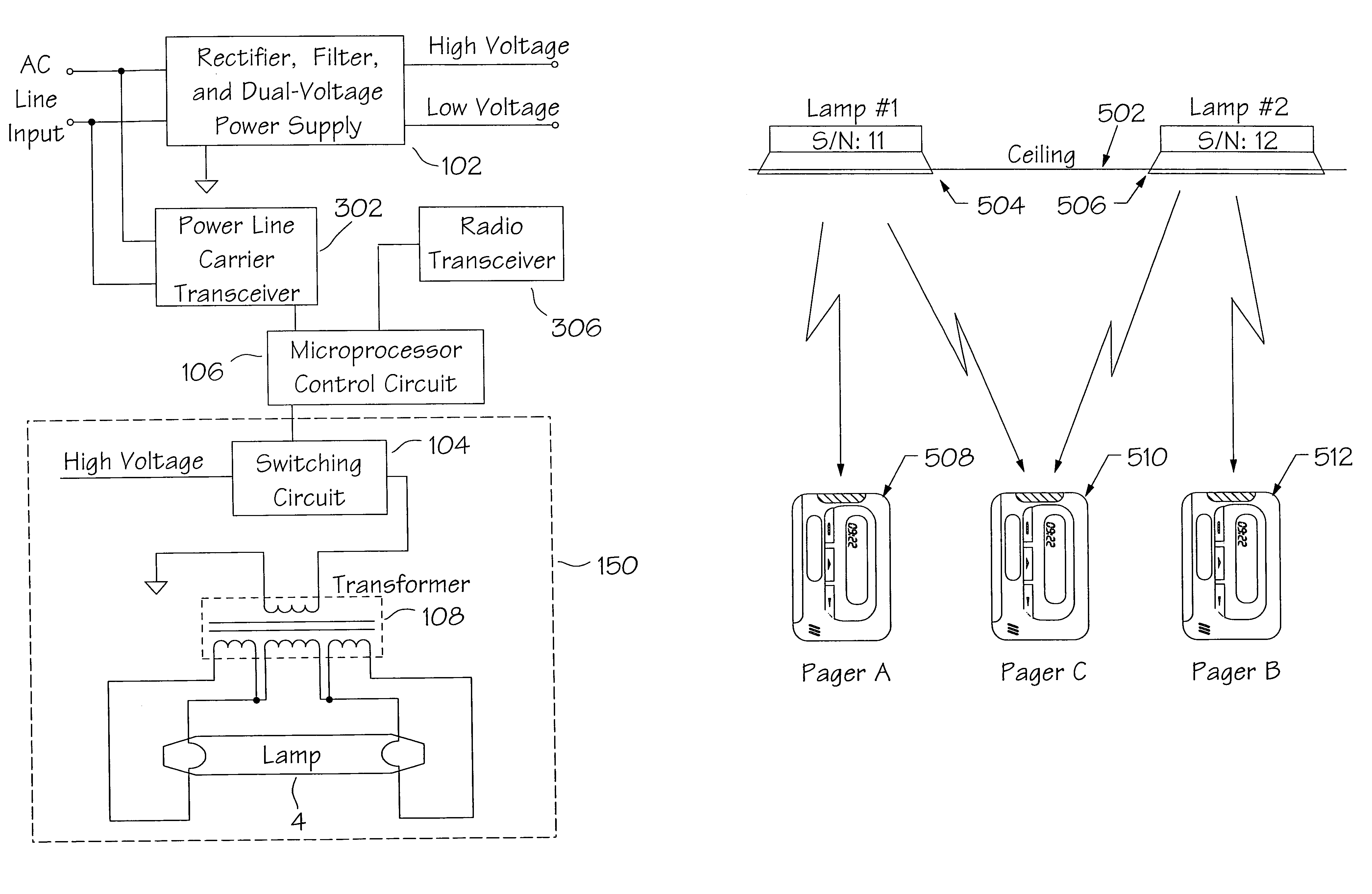
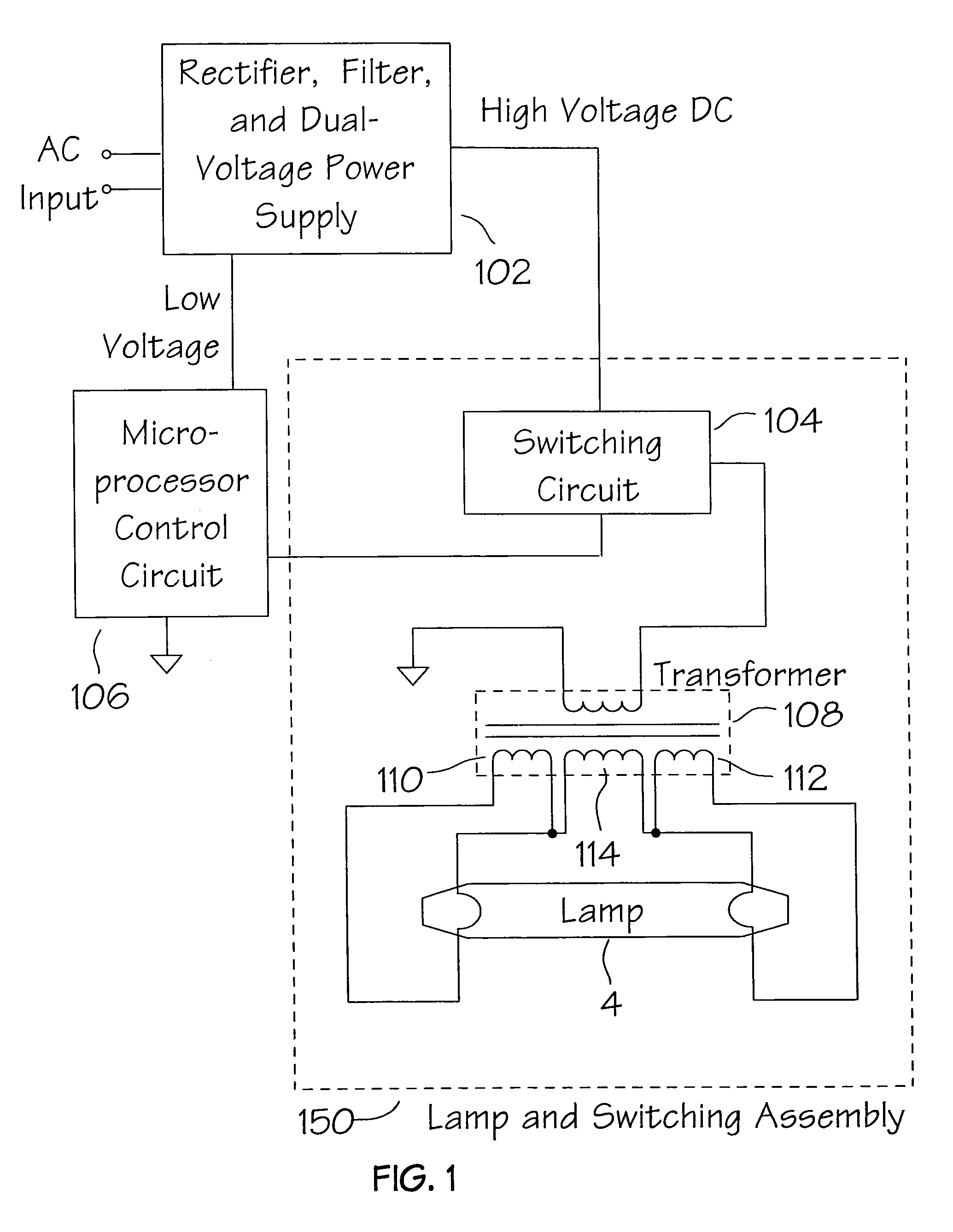
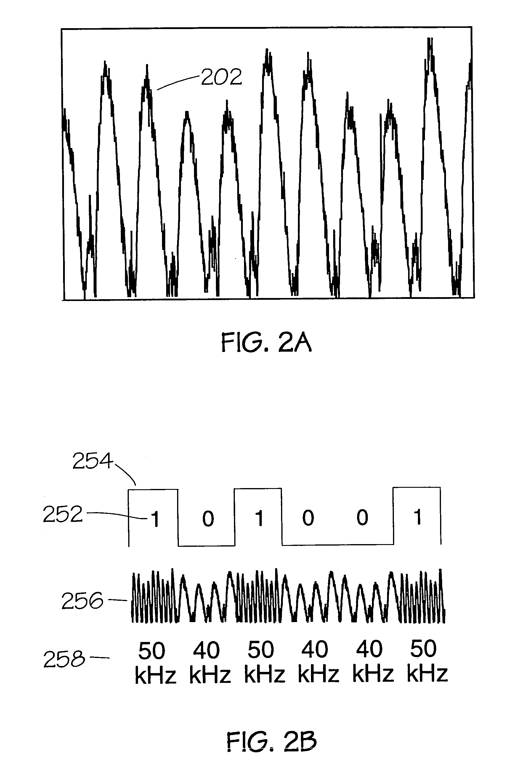
[0072]The main embodiment of the invention describes an fluorescent lamp lighting ballast that uses the output of the lamp or lamps under it's control to transmit data to one or more receivers. The configuration allows for the transmission of fixed data messages, such as a serial number, while allowing for the transmission of data messages that can be modified in the field. T...


PUM


Abstract

This invention relates to the zonal transmission of data by the modulation of the light output of arc lamps or discharge lamps; including the visible or invisible light output of fluorescent lamps, mercury vapor lamps, high or low-pressure sodium lamps, metal-halide based lamps, or other arc or discharge lamps. The method results in an easily installed, easily maintained, and economical to purchase, optical-wave communications system which exploits the existing infrastructure of a building or facility to facilitate the transmission of data in individual zones; thereby facilitating the transmission of wide-area as well as zonal-specific data to compatible receivers, and further facilitating the determination of location of remote devices or users, and the delivery or exchange of information or data, utilizing limited range transmission techniques.

Description

CROSS-REFERENCES TO RELATED APPLICATIONS[0001]This is one patent application anticipated when Provisional Patent Application Ser. No. 60 / 034,176 was filed the 2nd of Jan. 1997. Additionally, this application is also related to patent application Ser. No. 08 / 673,380 filed the 24 Jun. 1996, in that the devices in said application are operable and were envisioned to be used with the devices in this application.BACKGROUND[0002]1. Field of Invention[0003]This invention relates to the transmission of data by the modulation of the light output of fluorescent and other arc lamps; including the visible or invisible light output of fluorescent lamps, neon lamps, mercury vapor lamps, high or low-pressure sodium lamps, or other high-intensity discharge lamps, or any metal-halide based lamps.[0004]2. Description of Prior Art[0005]Several methods for the transmission and reception of data messages exists. Many of these have application to offices, factories, and to buildings or complexes of build...

Claims


Application Information

Patent Timeline
Patent Type & Authority Patents(United States)
IPC IPC(8): H04B10/00H05B37/00H05B37/02H05B41/392
CPCH04B10/1149H05B41/392H05B37/0272H04B10/116H05B47/19
Inventor FRANKLIN, PHILIP G.
Owner CONVERGENCE WIRELESS A CALIFORNIA CORP
Learn More