
Pendulum valve with a full range of position control

Inactive Publication Date: 2006-02-28
ENTEGRIS INC +1
View PDF25 Cites 40 Cited by
  • Summary
  • Abstract
  • Description
  • Claims
  • Application Information

AI Technical Summary

Benefits of technology

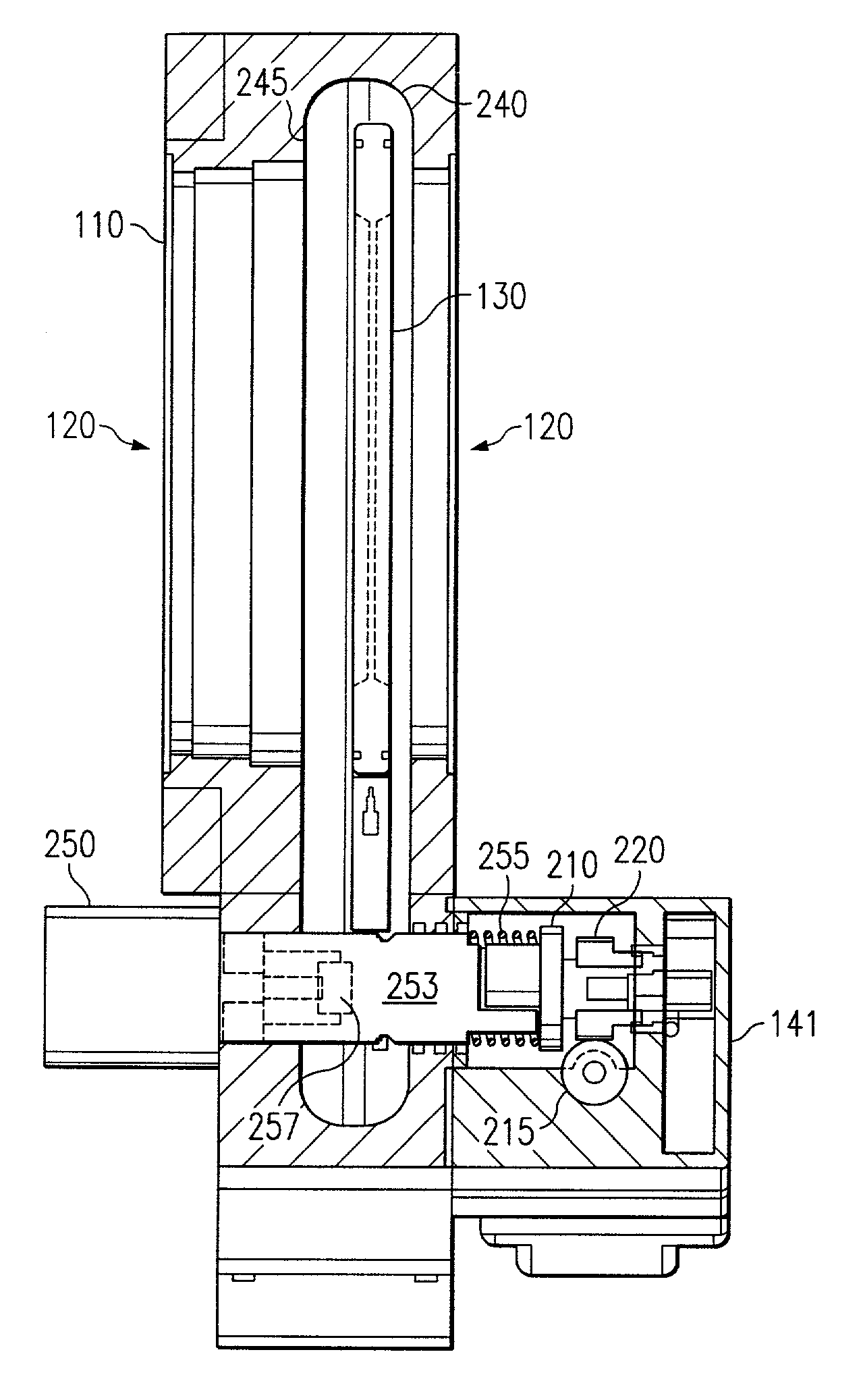
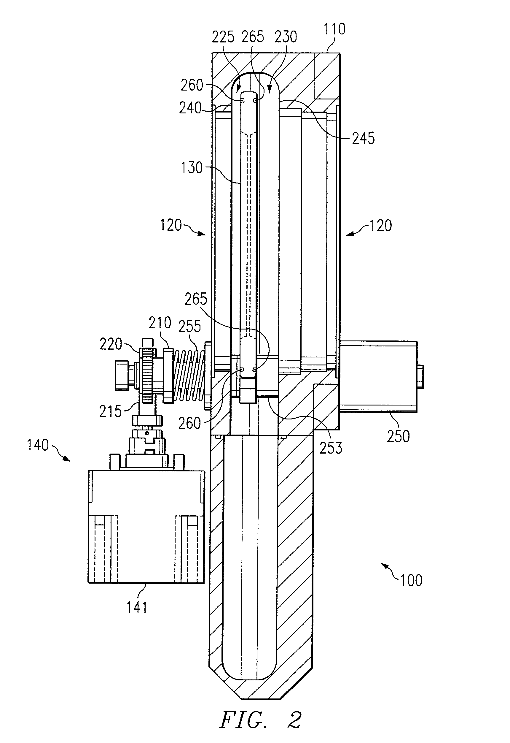
[0009]The present invention provides a pendulum valve that substantially eliminates or reduces disadvantages and problems associated with previously developed pendulum valves. More specifically, embodiments of the present invention provide a pendulum valve with a full range of normal position control. One embodiment of the pendulum valve can include a valve housing with a flow channel that allows the flow of a fluid (e.g., between a vacuum chamber to a turbo pump). The pendulum valve includes a valve body that is movable within the valve housing from a fully open position, which can allow the free flow of fluid, to at least one closed position which prevents fluid from flowing through the pendulum valve. In operation, the valve body can move within the valve housing generally perpendicular to the flow path from the fully open position to a partially open position that is generally axially aligned with the flow channel of the fluid. Furthermore, the valve body can move normal to the flow channel to any partially opened normal position and to at least one fully closed position. The pendulum valve can include a linear control mechanism that is operable to move the valve body normally to the flow channel and position the valve body in any one of a range of partially open positions.
[0010]In another embodiment of the present invention, the pendulum valve can include a valve housing with a flow channel and a valve body that is movable within the housing between a fully open position and a closed position. The valve body can also include a valve frame that is rotatable about a primary axis and a valve plate that is mounted to the valve frame such that the valve plate can rotate about a second axis of rotation. The second axis of rotation for the valve plate can lie in a plane that is generally orthogonal to the flow channel. Because the valve plate can rotate, the valve plate can self-align to form a seal with the valve housing even if the valve frame has become partially deformed.
[0011]Embodiments of the present invention provide an important technical advantage with respect to previous pendulum valves by allowing the valve body to be positioned throughout a range of continuous partially-opened positions, thereby providing for more accurate throttling of fluids in systems using the pendulum valve.

Problems solved by technology

However, these prior art systems are limited because pneumatics do not provide for accurate linear positioning, and in systems using pneumatics, the valve body can usually be linearly positioned only in the fully closed position (e.g., in the sealed position) or in one partially open position ready for rotation.
However, the valve body cannot be positioned over a range of continuous partially open positions to control the throttling of gas through the flow channel.
This system, however, is limited because it requires an extra valve and more valve controls to perform throttling functions.
Additionally, because of the extra valves, this prior art system is difficult to manufacture, service and maintain, causing valuable chip fabrication equipment to be shut down for hours while this type of pendulum valve is serviced or maintained.
However, even with two partially open positions, these valves do not provide sufficient throttling of gas flow for thin film coating processes that require accurate and uniform control of the thin film deposition.
Additionally, the pneumatics of these pendulum valves make the pendulum valves difficult to manufacture, service and maintain, again leading to hours of down time when the pendulum valve needs service or cleaning.
Another disadvantage of prior art systems is that, over time, the pressures experienced by the pendulum valve tend to bend the valve body.
Because the valve body is bent, the valve body may not form a tight seal even when the valve body is moved to the fully closed position, leading to significant leakage and a general degrading of the integrity of the vacuum in the vacuum chamber.
Thus, the ability of the prior art pendulum valves to create an adequate seal decreases over time as the valve bodies bend.

Method used


Image

  • Pendulum valve with a full range of position control
  • Pendulum valve with a full range of position control
  • Pendulum valve with a full range of position control

Examples


Embodiment Construction

[0023]Preferred embodiments of the present invention are illustrated in the FIGUREs, like numerals being used to refer to like and corresponding parts of various drawings.

[0024]Pendulum valves are commonly used in semiconductor manufacturing equipment to control chamber pressure. They can be located, for example, between high-vacuum chambers (e.g., on the order of one torr or less) and turbo pumps. A pressure sensor can monitor the gas pressure within a vacuum chamber or other apparatus and can communicate the pressure to a pressure controller, which can compare the detected pressure to a set point. A difference between the detected pressure and the set point can cause the pressure controller to generate an electrical signal to open or close the pendulum valve, thereby controlling chamber pressure.

[0025]Embodiments of the present invention provide a valve with a full range of normal position control. Because the valve body can be positioned in any one of a plurality of partially ope...


PUM


Abstract

Embodiments of the present invention provide a pendulum valve with a full range of normal position control. The pendulum valve can include a valve housing having a flow channel, and a valve body that is movable within the valve housing between a fully open position and at least one closed position. The pendulum valve can also include an electrical control mechanism operable to position the valve body in any one of a range of partially open positions.

Description

RELATED INFORMATION[0001]This application claims priority under 35 U.S.C. § 119(e) to provisional patent application No. 60 / 286,790 entitled “Pendulum Valve with Accurate Control In Throttling and Thrusting,” filed Apr. 25, 2001, which is hereby fully incorporated by reference.TECHNICAL FIELD OF THE INVENTION[0002]The present invention relates generally to pendulum valves and more particularly to a pendulum valve with a full range of normal position control to allow for a continuous range of partially open positions.BACKGROUND OF THE INVENTION[0003]In semiconductor manufacturing, as the size of silicon wafers increases and the size of semiconductor devices decreases, there is an ever greater need for the application of uniform thin films to the silicon wafers. However, the uniformity of a thin film is strongly dependent upon precise pressure control of the gases within the semiconductor manufacturing equipment.[0004]Pendulum valves have been used in high-purity gas delivery systems ...

Claims


Application Information

Patent Timeline
IPC IPC(8): F16K3/18F16K3/06F16K3/10F16K51/02
CPCF16K3/06F16K51/02F16K3/10
Inventor CHENG, SHIYUAN DENNY
Owner ENTEGRIS INC
Learn More