Integrated three function valve

a three-function valve and integrated technology, applied in the direction of fluid couplings, servomotor parallel arrangements, servomotors, etc., can solve the problems of failure detection and bypass time not being sufficient, affecting the protection of the failed ram, and reducing the load rate capacity

Inactive Publication Date: 2006-02-28
BELL HELICOPTER TEXTRON INC
View PDF4 Cites 17 Cited by
  • Summary
  • Abstract
  • Description
  • Claims
  • Application Information

AI Technical Summary

Benefits of technology

[0011]Therefore, it is an object of the present invention to provide a rotor control system that provides full triple redundancy.
[0018]The present invention provides many significant benefits and advantages, including: (1) bypass valve function is redundant and independent; (2) confirmation of redundant bypass valve operation is available during PFBIT, and continuous health monitoring is possible in certain applications; (3) PRV function is redundant and independent; (4) confirmation of PRV operation is available during PFBIT, and continuous health monitoring is possible in certain applications (5) redundant delta pressure sensors are provided to permit continuous cross checking of accuracy; (6) delta pressure sensors are robust and free from common mode changes in accuracy; and (7) additional actuator redundancy does not require any additional wiring or changes to existing FCC interfaces.

Problems solved by technology

The degradation in load rate capacity resulting from the combination of driving flow across the relief valve on the failed cylinder and increased friction from bending is not acceptable.2. An EHSV sticking at null position combined with the sticking of the pressure relief valve (PRV), a dormant failure.
Although this condition can be overridden by a bypass valve, it is considered that the total time required between failure detection and achieving bypass is not adequate to protect the failed ram from a spike of overpressurization.
This condition is a greater problem for the triplex ram than for the duplex ram, as the peak load can be three times the design stall, i.e., two active rams at stall plus air load; compared to twice the stall, i.e., one active ram at stall plus air load.
If the ram on the remaining system contains a PRV that opens at pressures below system operating pressure, control of the actuator can be lost.
However, this subjects the actuator and structure to severe fatigue loads.4. In the event of the loss of one ram due to FCC or hydraulic system failure, the two functioning rams should equally support actuator flight loads.
However, if a failure mode of a delta pressure sensor results in a pressure indication opposite in direction of the actual ram load, a force fight between the remaining two actuators can result in the frequency response of the actuator becoming severely degraded.
In addition to these double failure modes, a change of sensitivity of a differential pressure sensor can lead to increased fatigue due to an increased force fight between the triple actuators.

Method used


Image

  • Integrated three function valve
  • Integrated three function valve
  • Integrated three function valve

Examples


Embodiment Construction

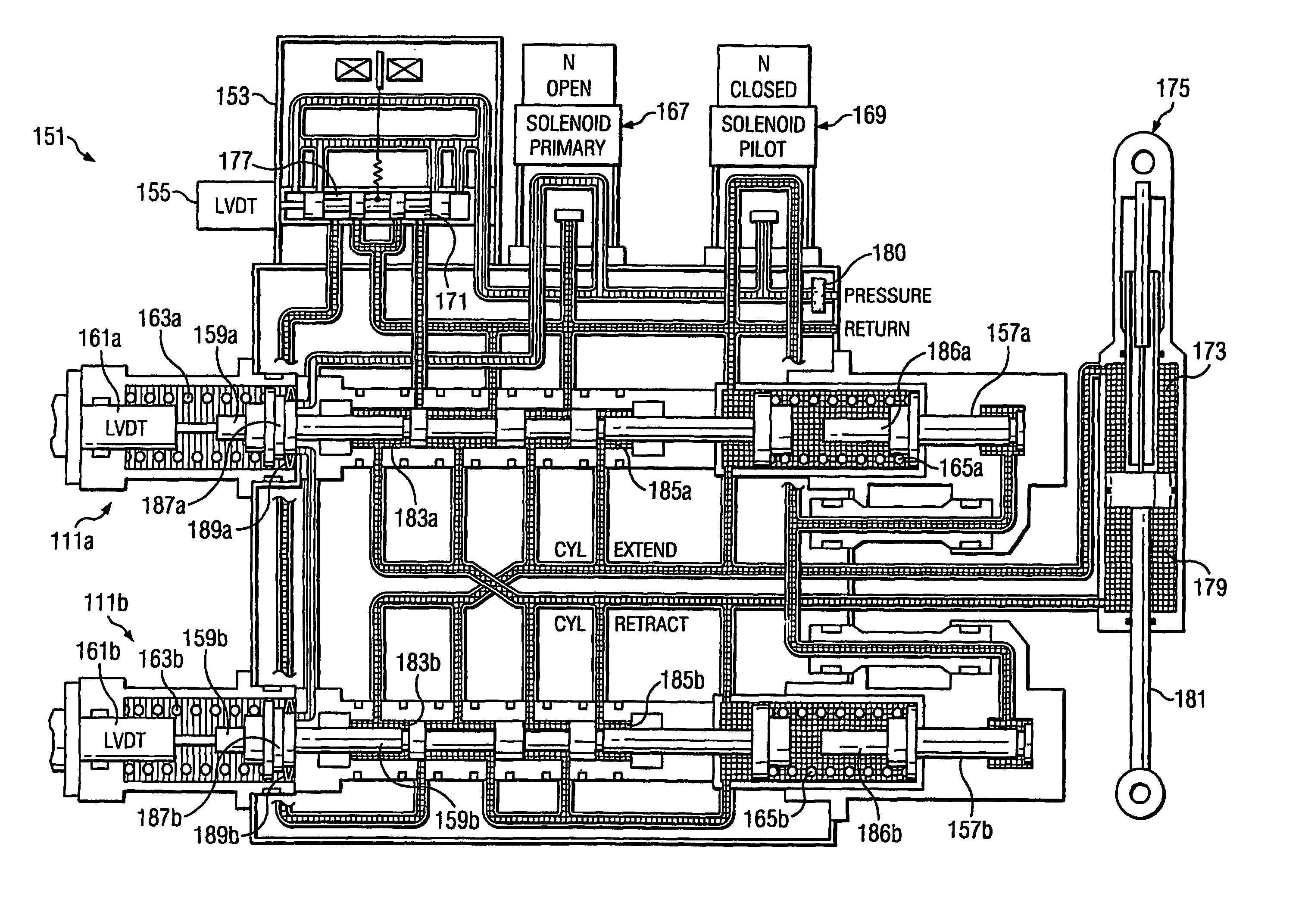
[0027]Referring now to FIGS. 3A–3F in the drawings, the preferred embodiment of an ITFV 111 according to the present invention is illustrated. ITFV 111 utilizes two hydraulic spools to combine the functions of bypass valve, pressure relief valve, and delta pressure transducer into a simple and compact assembly. When used as a matched pair in a collective actuator, ITFV's 111 provide redundant bypass valve, pressure relief valve, and delta pressure transducer functionality. This allows certain redundancy and monitoring requirements to be met with fewer springs, hydraulic spools, and pistons than other actuator designs.

[0028]Referring now to FIG. 4 in the drawings, three collective actuators 113 are shown installed in the left hand nacelle of a tiltrotor aircraft. Each collective actuator 113 utilizes a matched pair of ITFV's 111, and is configured to create unequal extend and retract areas to better match predicted flight loads and reduce transient effects. Flight loads are predomina...


PUM


Abstract

An integrated three function valve (ITFV) that combines the functions of a bypass valve (e.g. 183a, 185a, 161a) into a single assembly is disclosed. The ITFV allows continued operation after any two failures. With the integrated three function valve, no combination of electrical or hydraulic component failures, regardless of expected failure rate, will prevent an actuator from continued safe operation

Description

[0001]This application claims the benefit of Provisional Application No. 60 / 381,184, filed May 16, 2002.TECHNICAL FIELD[0002]The present invention relates to actuation systems for aircraft. In particular, the present invention relates to fly-by-wire rotor actuation systems for tiltrotor aircraft.DESCRIPTION OF THE PRIOR ART[0003]Compared with conventional fixed wing commercial aircraft, the task of designing helicopter flight control systems to avoid flight critical failure modes is considerably more challenging. For typical fixed wing commercial aircraft, flight control system redundancy can be provided through the application of multiple independently actuated surfaces. An example of this methodology is the use of two or three ailerons per wing. Configured in this manner, continued safe flight is achieved in the event of an aileron becoming uncontrollable or seized.[0004]On the other hand, in helicopters and tiltrotor aircraft, application of multiple independently actuated rotors...

Claims


Application Information

Patent Timeline
Patent Type & Authority Patents(United States)
IPC IPC(8): F15B11/08F15B13/10B64C13/42B64C27/28B64C29/00F15B18/00F15B20/00
CPCB64C13/42B64C27/28F15B20/008F15B18/00F15B20/002B64C29/0033Y10T137/87209Y10T137/87201B64C13/504
Inventor FENNY, CARLOS A.SCHULTZ, DAVID P.PRICE, IAN L.CURD, DAVID A.
Owner BELL HELICOPTER TEXTRON INC
Why Eureka
Try Eureka