
Symbol timing tracking and method therefor

a timing tracking and symbol technology, applied in the field of data communication systems, can solve the problems of inability to properly acknowledge and process data, time drift creates significant data errors, and the approach proposed by patenaude et al. is complex and requires a significant amount of hardware and calculations

Active Publication Date: 2006-02-21
NXP USA INC
View PDF5 Cites 15 Cited by
  • Summary
  • Abstract
  • Description
  • Claims
  • Application Information

AI Technical Summary

Problems solved by technology

This clock rate difference causes the receiver to see the incoming data at either faster or slower than expected, hereafter referred to as “timing drifting”, thus being unable to properly acknowledge and process the data.
However, for a communication system with high symbol rate and long packet size, such as the Bluetooth High Rate and the 802.11b standards, the timing drift creates significant data errors.
The approach proposed by Patenaude et al. is complex and requires a significant amount of hardware and calculations.
Therefore, power consumption and the cost of the tracking circuitry are significant deterrents to using Patenaude's approach.

Method used


Image

  • Symbol timing tracking and method therefor
  • Symbol timing tracking and method therefor
  • Symbol timing tracking and method therefor

Examples


Embodiment Construction

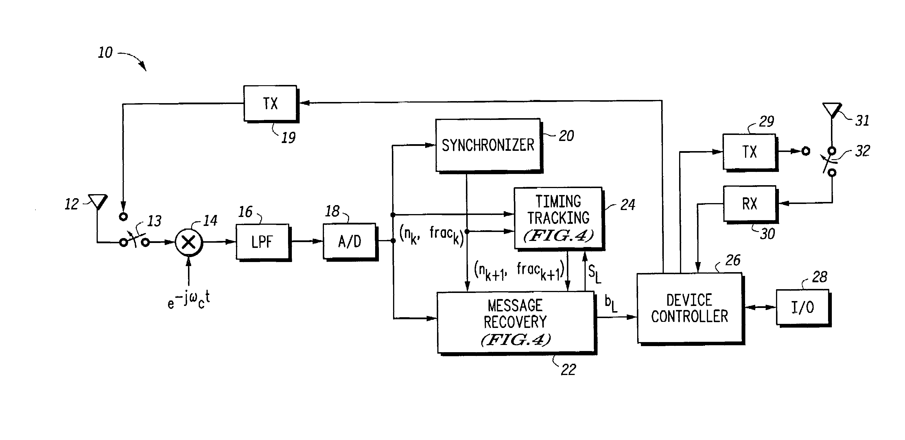
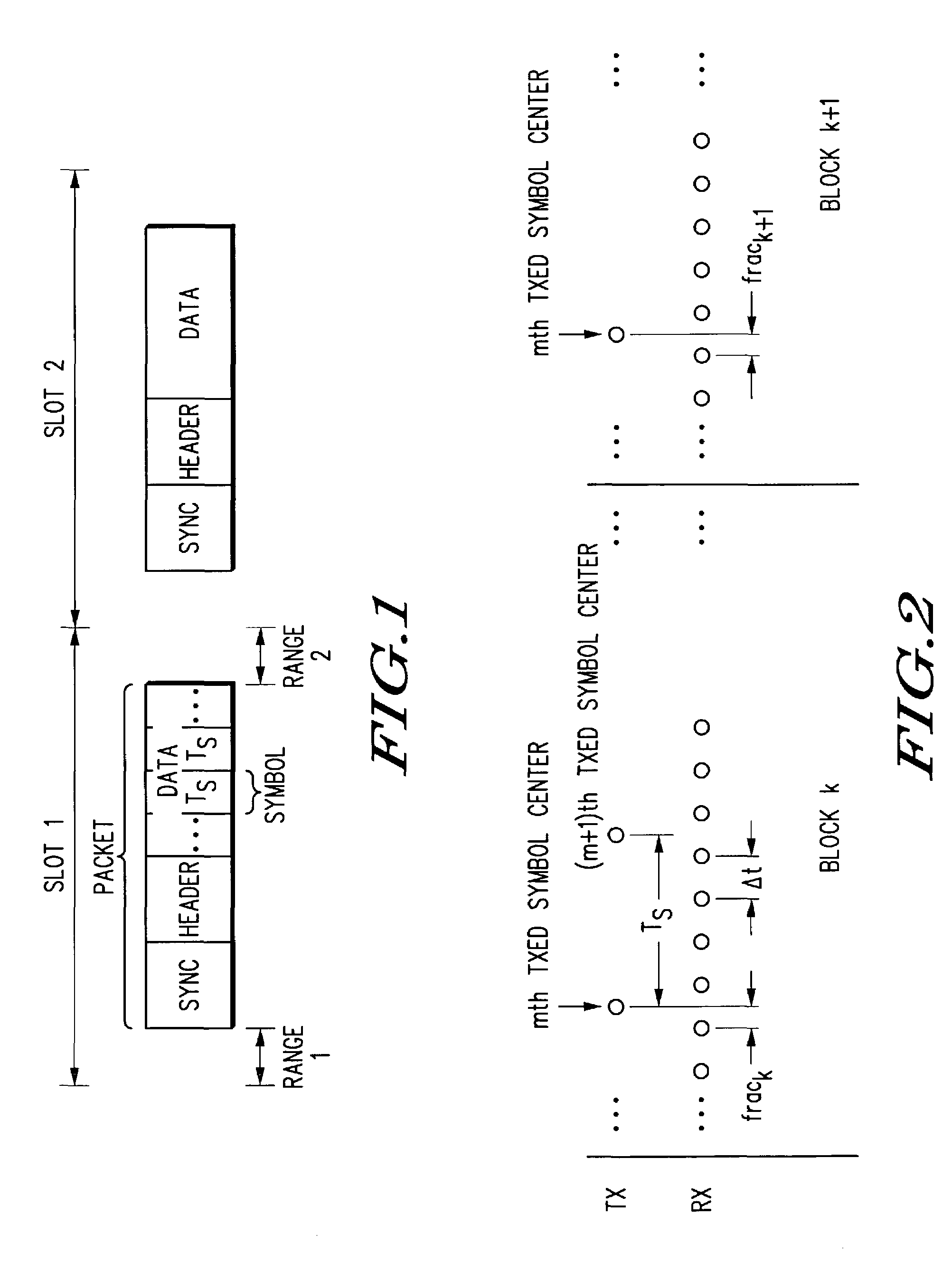
[0011]Illustrated in FIG. 1 is a packet diagram of two neighboring packets transmitted in two successive time slots, Slot 1 and Slot2. In the illustrated form, each of the slots lasts longer than the length of each packet to prevent packet collision. Within each packet are distinct fields. A synchronization field, SYNC, is at the beginning of the packet. The SYNC field is followed by a Header field. After the Header is a data field. The data field contains a plurality of individual symbols, labeled Ts. The data packet must begin in Slot 1 in a specified range or at least by the end of a time range designated as Range 1. Further, the data packet must end at any time within a second time range or at least by the end of a time designated as Range 2. Although only two specific data symbols are illustrated in FIG. 1, it should be well understood that a large number of data symbols may be included within the data field of each packet as indicated by the dots in FIG. 1. Additionally, each ...


PUM


Abstract

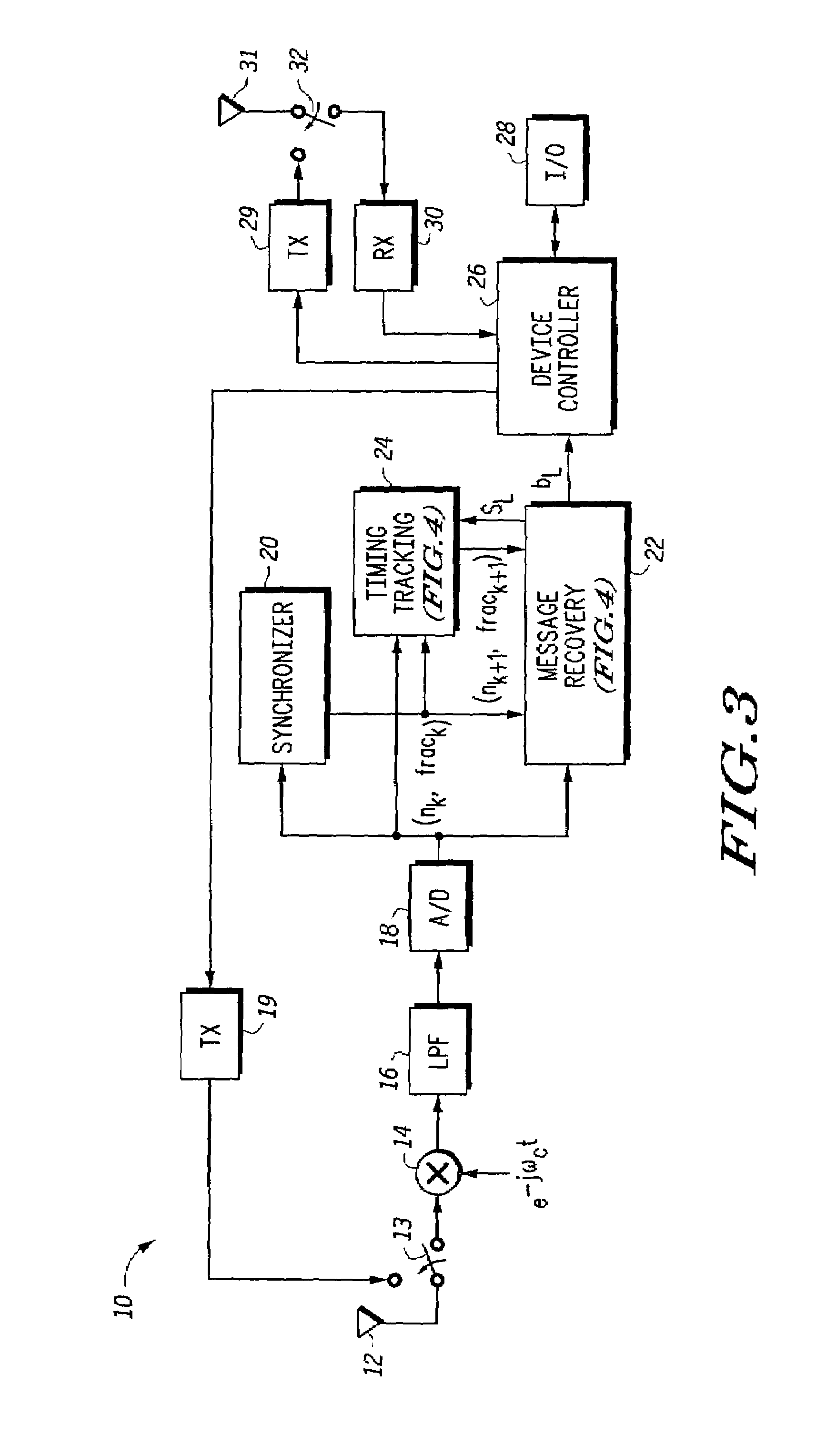
A system and method in a communication device (10) uses timing tracking to correct timing drifting due to the difference in frequency of a transmitter clock and a receiver clock. With the timing tracking, correlation values of three consecutive samples are calculated using the receive signal and the recovered symbols and then summed. A timing signal, (nk, frack) is updated based upon a metric calculated from a previous correlation value, R−1, present correlation value (R0) and a next con-elation value (R+1). Adjustment of timing signal is based on the relative location with respect to the current timing of a peak of a second order polynomial curve formed by the first correlation value R−1, the second correlation value R0 and the third correlation value R+1.

Description

FIELD OF THE INVENTION[0001]This invention relates generally to data communication systems, and more specifically, to clock timing tracking within data communication systems.BACKGROUND OF THE INVENTION[0002]Data communication systems typically utilize a transmitting device that operates under control of a first clock and an independent receiving device that operates under control of a second clock. Although the first clock and the second clock may be designed to operate at exactly the same desired frequency, the reality is that there is clock speed variation associated with each clock. Therefore, the transmitting device and the receiving device have a clock rate difference. This clock rate difference causes the receiver to see the incoming data at either faster or slower than expected, hereafter referred to as “timing drifting”, thus being unable to properly acknowledge and process the data.[0003]In packet based transmission systems, generally there is a known synchronization bit pa...

Claims


Application Information

Patent Timeline
IPC IPC(8): H04L27/06H04L7/02
CPCH04L7/0062H04L7/0029
Inventor CHEN, WEIZHONG
Owner NXP USA INC
Learn More