
Apparatus and method for recording and reproducing information to and from an optical storage medium

a technology of optical storage medium and apparatus, applied in the direction of optical recording/reproducing/erasing methods, optical beam sources, instruments, etc., can solve the problems of reducing the amount of information recordable, deteriorating the sn ratio of reproduced information, and reducing the size of the optical system for recording and reproduction. , to achieve the effect of reducing the amount of information

Inactive Publication Date: 2006-02-21
OPTWARE
View PDF5 Cites 29 Cited by
  • Summary
  • Abstract
  • Description
  • Claims
  • Application Information

AI Technical Summary

Benefits of technology

[0011]It is an object of the invention to provide an optical information recording apparatus and method, an optical information reproducing apparatus and method, and an optical information recording / reproducing apparatus and method for recording or reproducing information through the use of holography, which allow a small configuration of the optical system for recording or reproduction without causing a reduction in the amount of information.
[0065]in the recording step, each of the recording-specific reference light having a predetermined first direction of polarization and the information light having a second direction of polarization different from the first direction of polarization is optically rotated in directions different between respective half areas of a cross section of a beam thereof to cause each of the information light and the recording-specific reference light to have directions of polarization different between the respective areas such that the direction of polarization of the information light yet to impinge on the reflecting surface coincides with that of the recording-specific reference light reflected by the reflecting surface, and the direction of polarization of the recording-specific reference light yet to impinge on the reflecting surface coincides with that of the information light reflected by the reflecting surface,

Problems solved by technology

Conventional optical information recording / reproducing methods that use holography have had a problem that the reproduced information deteriorates in SN ratio if reproduction-specific reference light is also incident on a photodetector for detecting reproduction light.
Nevertheless, when the information light and the recording-specific reference light are allowed to be incident on the recording medium with a predetermined angle therebetween at the time of recording so as to spatially separate the reproduction light and the reproduction-specific reference light from each other at the time of reproduction as described above, there arises a problem that the optical system for recording and reproduction becomes greater in size.
This technique, however, has a problem that a special optical system is required for allowing the information light and the reference light to converge at different positions.
This technique, however, has a problem that the amount of information recordable is reduced because information can be carried by only a part of the cross section of the beam projected onto the recording medium.

Method used


Image

  • Apparatus and method for recording and reproducing information to and from an optical storage medium
  • Apparatus and method for recording and reproducing information to and from an optical storage medium
  • Apparatus and method for recording and reproducing information to and from an optical storage medium

Examples


Embodiment Construction

[0087]Hereinafter, an embodiment of the invention will be described in detail with reference to the drawings.

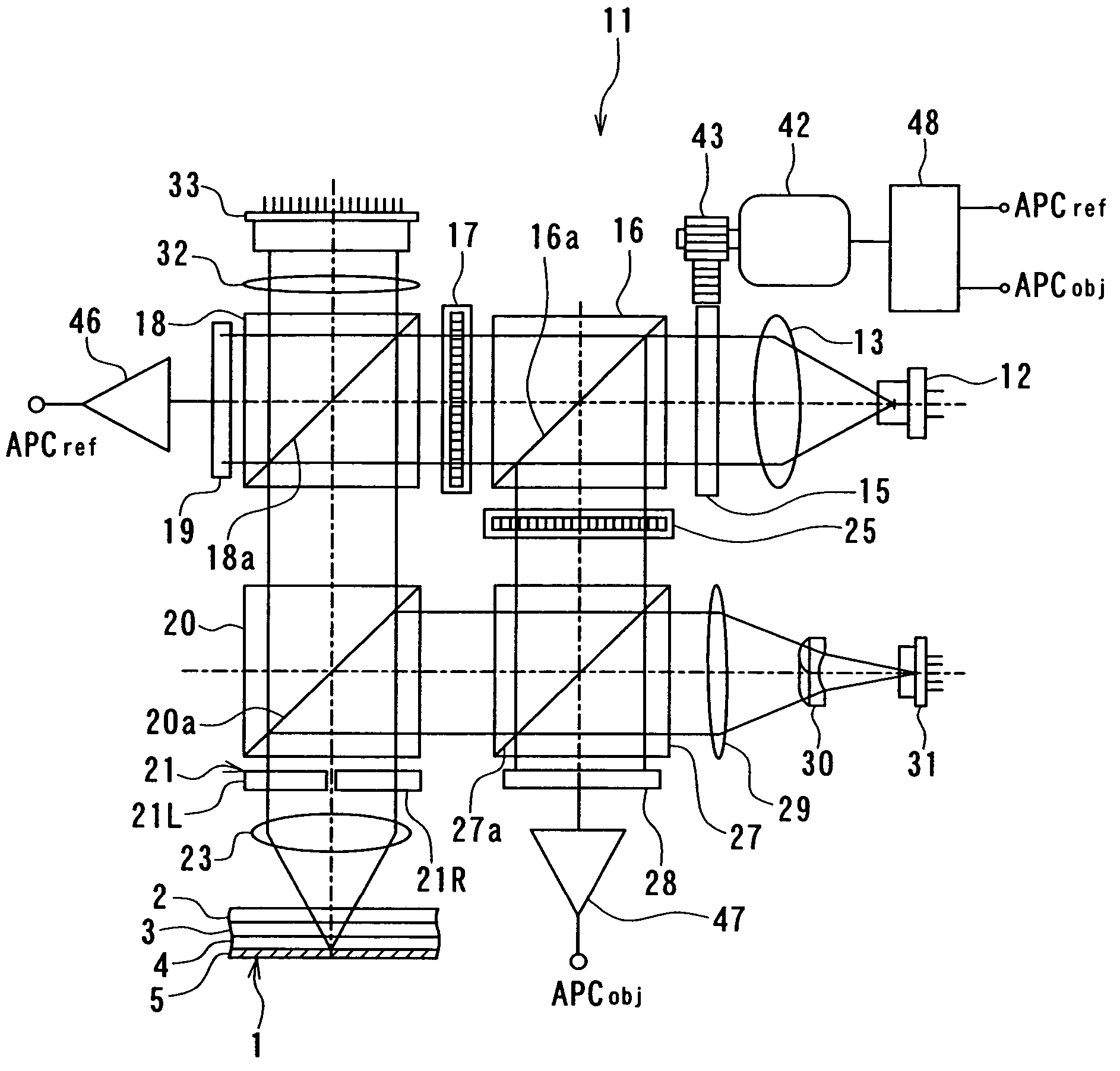
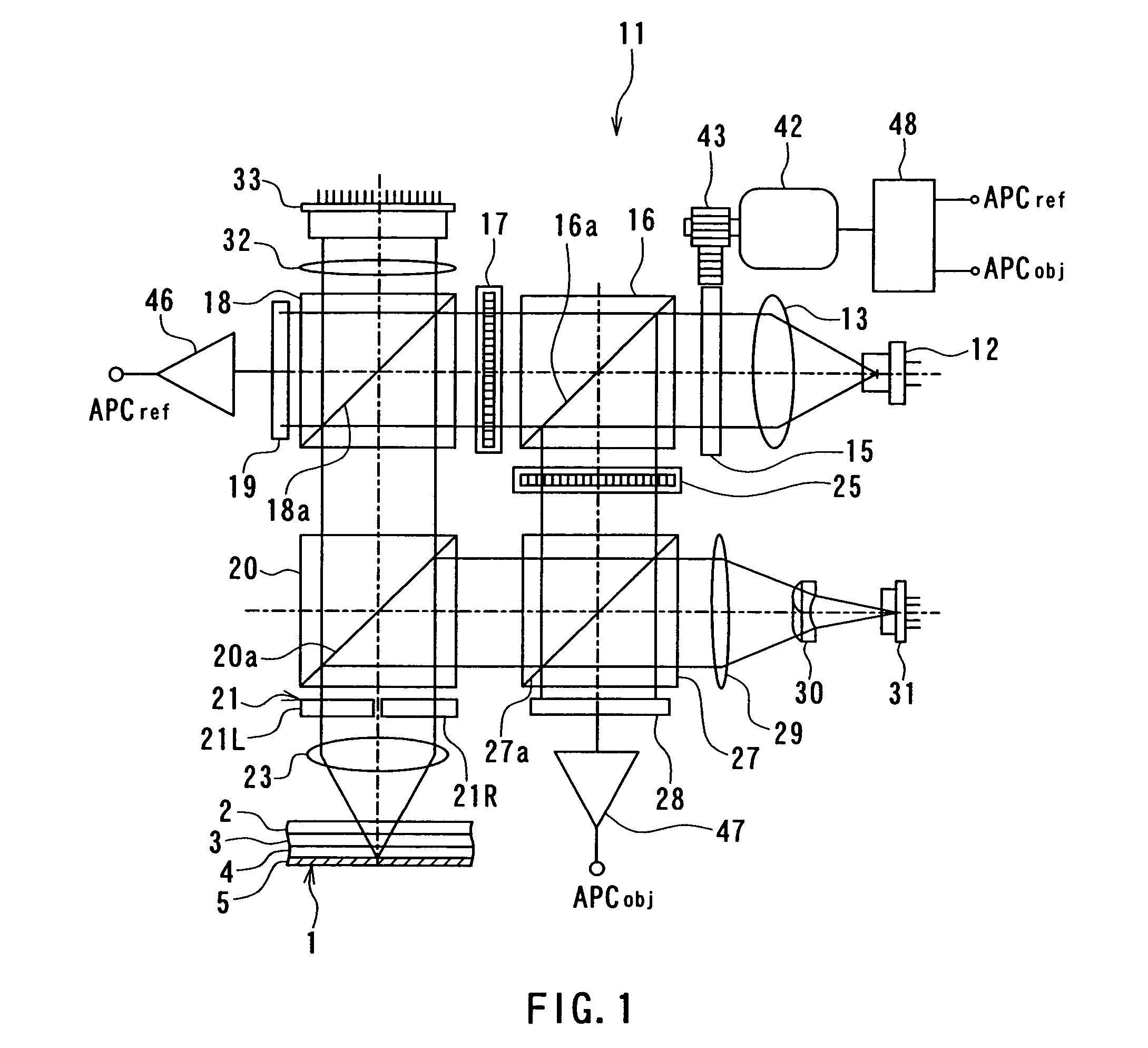
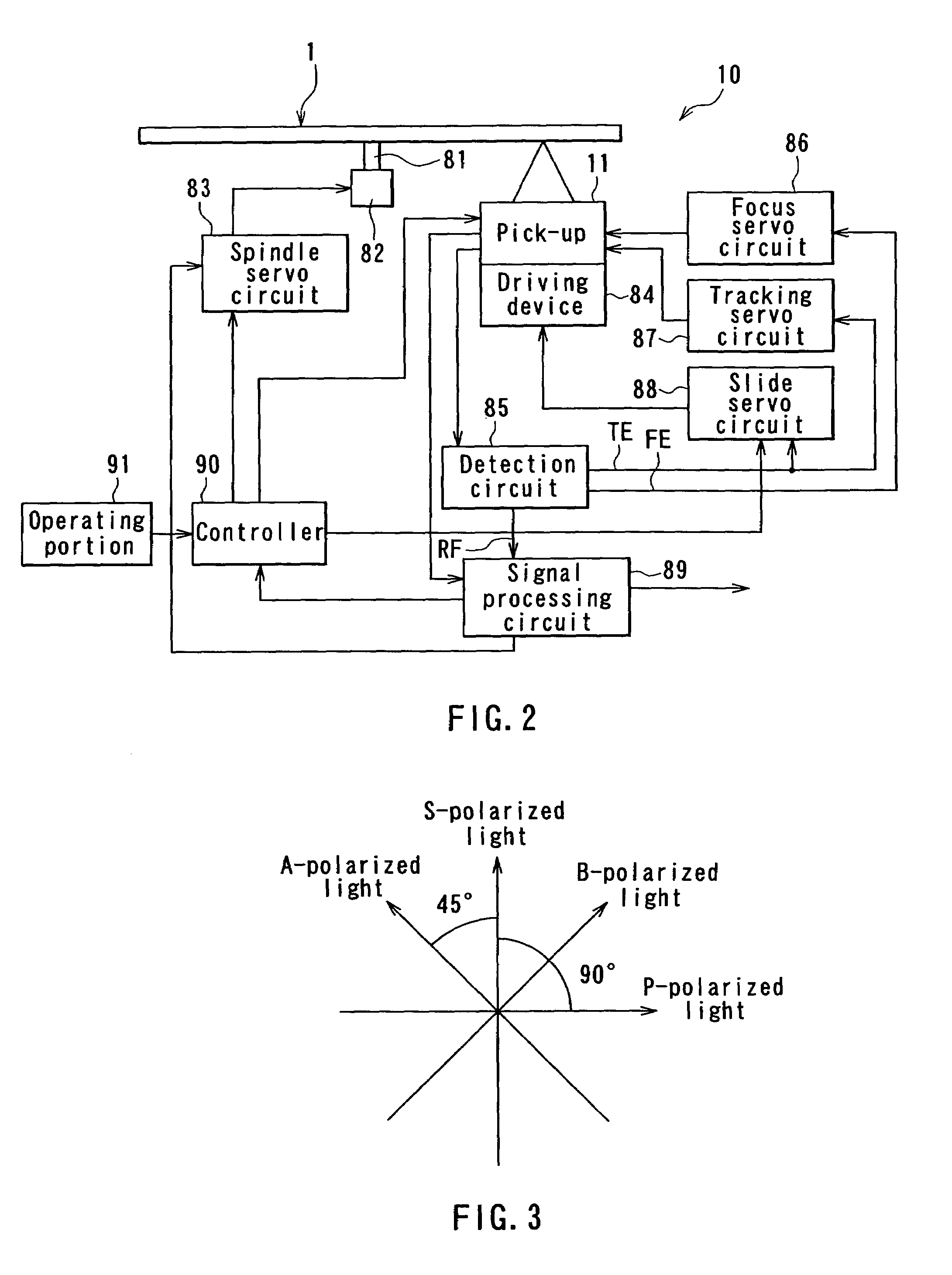
[0088]First, with reference to FIG. 1 and FIG. 2, description will be given of a configuration of an optical information recording / reproducing apparatus acting as an optical information recording apparatus and an optical information reproducing apparatus according to the embodiment of the invention. FIG. 1 is an explanatory diagram illustrating a configuration of a pick-up of the optical information recording / reproducing apparatus according to the present embodiment. FIG. 2 is a block diagram illustrating a general configuration of the optical information recording / reproducing apparatus according to the embodiment.

[0089]First, with reference to FIG. 1, description will be given of a configuration of an optical information recording medium used in the present embodiment. The optical information recording medium 1 of the embodiment comprises a disk-like transparent substrate 2 ...


PUM

PropertyMeasurementUnit
angleaaaaaaaaaa
phaseaaaaaaaaaa
spatially modulated phaseaaaaaaaaaa

Abstract

Holographic recording and reproducing using a compact configuration provides no reduction in the recording / reproducing capability. Information light and recording-specific reference light having a spatially modulated phase are generated and projected onto an optical recording medium coaxially that converge on a reflecting surface of a recording medium. P-polarized recording-specific reference light and S-polarized information light are each optically rotated by a two-way split optical rotation plate in directions different between respective half areas of the cross section of the beam thereof. An interference paffern resulting from interference between information light yet to impinge on the reflecting surface and recording-specific reference light reflected by the reflecting surface and an interference pattern resulting from interference between recording-specific reference light yet to impinge on the reflecting surface and information light reflected by the reflecting surface are recorded in the information recording layer.

Description

[0001]This application is a 371 of PCT / JP01 / 05590 Jun. 28, 2001.TECHNICAL FIELD[0002]The present invention relates to an optical information recording apparatus and method for recording information on an optical information recording medium through the use of holography, an optical information reproducing apparatus and method for reproducing information from an optical information recording medium through the use of holography, and an optical information recording / reproducing apparatus and method for recording information on an optical information recording medium and reproducing the information from the optical information recording medium through the use of holography.BACKGROUND ART[0003]In general, holographic recording for recording information in a recording medium through the use of holography is performed by superimposing light that carries image information on reference light within the recording medium and by writing a resultingly generated interference pattern into the rec...

Claims


Application Information

Patent Timeline
Patent Type & Authority Patents(United States)
IPC IPC(8): G11B7/0065G03H1/04G03H1/00G03H1/12G03H1/22G11B7/125G11B7/128G11B7/135G11B7/1365G11C13/04
CPCG03H1/00G11C13/042G11B7/0065G11B7/083G11B7/128G11B7/1365G03H2001/2675G03H2210/22G03H2222/31G03H2250/42
Inventor HORIMAI, HIDEYOSHI
Owner OPTWARE
Learn More