
Position sensor fault tolerant control for automotive propulsion system

a technology of position sensor and automotive propulsion system, which is applied in the direction of motor/generator/converter stopper, dynamo-electric converter control, instruments, etc., can solve the problems of loss of propulsion fault, driver stranded without moving the vehicle, and the traction system of the vehicle provides gracefully degraded performan

Active Publication Date: 2006-02-21
GM GLOBAL TECH OPERATIONS LLC
View PDF10 Cites 105 Cited by
  • Summary
  • Abstract
  • Description
  • Claims
  • Application Information

AI Technical Summary

Benefits of technology

[0006]A control system for a motor including a rotor comprises a sensorless sensor module that includes a first estimator module that generates a first rotor position signal based on a first sensorless approach and a second estimator module that generates a second rotor position signal based on a second sensorless approach. A selector selects the first rotor position signal for rotor speeds below a first ro...

Problems solved by technology

In a typical drive system, failure of the position / speed sensor will cause a loss of propulsion fault.
This would leave the driver stranded with no means of moving the vehicle.
As a result, the traction system of the vehicle provides gracefully degraded performance according to the faults.
Position / speed sensors generally have high cost and low reliability.
The position sensor presents a single point failure that can cause a loss of propulsion.
The rotor flux estimator based IFOC has limitations at low speeds.
The open loop V / Hz type control suffers from poor performance as compared to IFOC controls.

Method used


Image

  • Position sensor fault tolerant control for automotive propulsion system
  • Position sensor fault tolerant control for automotive propulsion system
  • Position sensor fault tolerant control for automotive propulsion system

Examples


Embodiment Construction

[0025]The following description of the preferred embodiment(s) is merely exemplary in nature and is in no way intended to limit the invention, its application, or uses. For purposes of clarity, the same reference numbers will be used in the drawings to identify similar elements. As used herein, the term module and / or device refers to an application specific integrated circuit (ASIC), an electronic circuit, a processor (shared, dedicated, or group) and memory that execute one or more software or firmware programs, a combinational logic circuit, or other suitable components that provide the described functionality.

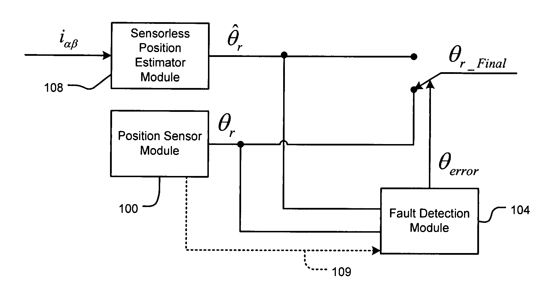
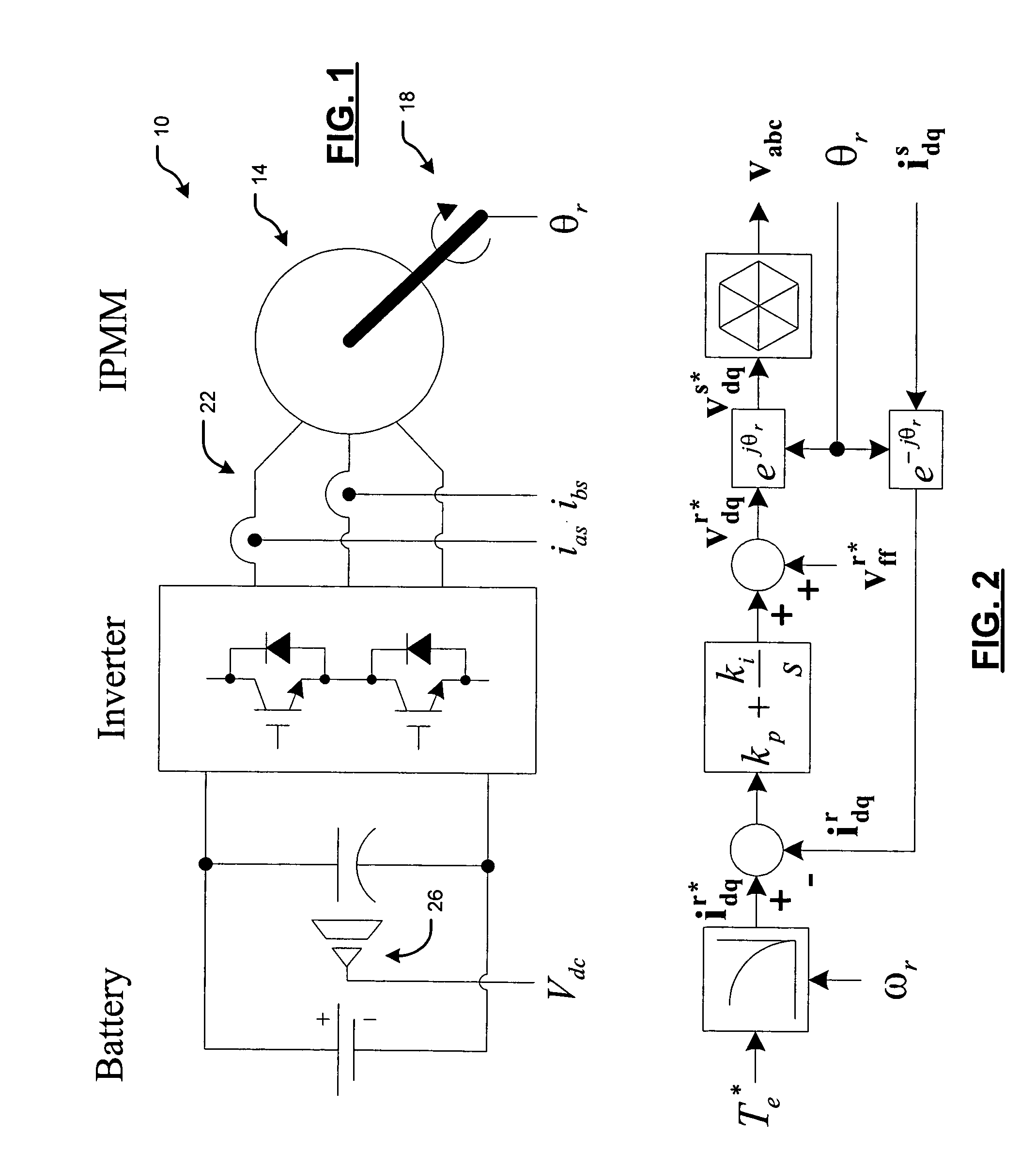
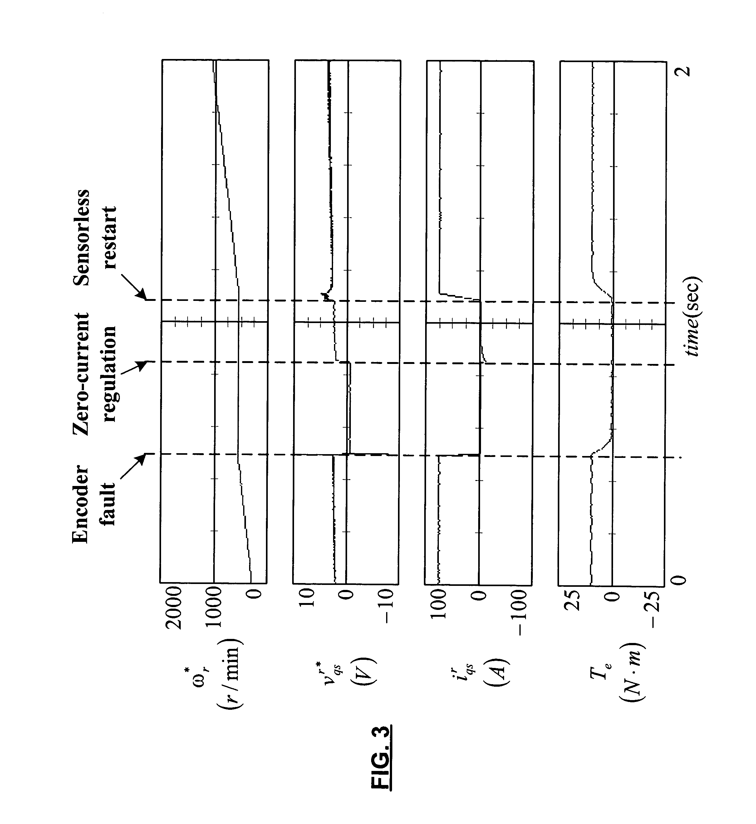
[0026]The present invention switches over to sensorless-based motor control algorithm upon detection of a position / speed sensor failure to preserve at least a minimal amount of propulsion torque. A sensorless position estimator module uses a saliency-based technique at low speeds and a back-EMF based technique at high speeds. With this combination, the sensorless position es...


PUM


Abstract

A control system for a motor including a rotor comprises a sensorless sensor module that includes a saliency-based estimator module that generates a first rotor position signal based on saliency and a back electromotive force (emf) estimator module that generates a second rotor position signal based on back emf. A selector selects the first rotor position signal for rotor speeds below a first rotor speed and the second rotor position signal for rotor speeds above the first rotor speed. A rotor position sensor senses a position of the rotor and generates a third rotor position signal. A fault detection module senses faults in the rotor position sensor and outputs the third rotor position signal when a fault is not detected and one of the first and second rotor position signals when the fault is detected. An indirect field oriented control (IFOC) system controls the motor based on a selected one of the first, second and third rotor position signals.

Description

FIELD OF THE INVENTION[0001]The present invention relates to motors, and more particularly to the control of motors using sensor-based and sensorless approaches.BACKGROUND OF THE INVENTION[0002]Electric motor drives are becoming more prevalent in automotive systems every year. As hybrid and electric vehicles become more popular, the quantity of automotive AC drive systems in the field will grow rapidly. They can be used in either electric or hybrid vehicles as a part the propulsion system. In a typical application, the motor drive requires a position or speed sensor device to properly control the motor. Fault tolerance and robustness are important features to insure trouble-free operation of the vehicle. In a typical drive system, failure of the position / speed sensor will cause a loss of propulsion fault. This would leave the driver stranded with no means of moving the vehicle.[0003]Most fault detection and fault tolerant approaches focus on faults of power semiconductors in an inve...

Claims


Application Information

Patent Timeline
IPC IPC(8): H02P3/00
CPCB60L3/0038Y02T10/642H02P2203/05Y02T10/64
Inventor SCHULZ, STEVEN E.GLEASON, SEAN EPATEL, NITINKUMAR R.NAGASHIMA, JAMES M.JEONG, YU-SEOKSUL, SEUNG KIMILANI, MICHAEL
Owner GM GLOBAL TECH OPERATIONS LLC
Learn More