
Seat-load measuring apparatus

a technology for measuring apparatus and seat load, which is applied in the direction of apparatus for force/torque/work measurement, pedestrian/occupant safety arrangement, instruments, etc., can solve the problem of insufficient strength of the pin bracket 108/b>, and achieve the effect of reliably supporting a heavy load and increasing mounting flexibility

Active Publication Date: 2006-02-21
HONDA MOTOR CO LTD +1
View PDF6 Cites 5 Cited by
  • Summary
  • Abstract
  • Description
  • Claims
  • Application Information

AI Technical Summary

Benefits of technology

[0006]One object of the present invention is to provide a seat-load measuring apparatus that increases mounting flexibility without increasing layout restrictions and that can more reliably support a heavy load imposed, for example, in a vehicle collision.
[0012]Since a heavy load produced, for example, in a vehicle collision is supported by the load support member in this way, the rail bracket means has a sufficient strength to withstand such a heavy load. Consequently, there is no need to increase the strength of the rail bracket. As a result, the dimensions of the rail bracket do not need to be increased.
[0013]Therefore, the rail bracket can be made compact, layout restrictions are lightened, and mounting flexibility is increased.
[0014]In particular, when a heavy load is imposed on the seat rail, it may be supported by the contact of the arc portion of the load-support member made of a belt-shaped plate with the stopper pin. Therefore, the heavy load is reliably supported with a simple structure.
[0015]In another aspect, the vehicle seat can be stably supported on the vehicle body by fixing the seat bracket to the vehicle body, and the load on the vehicle seat can be more precisely detected by the load sensor.

Problems solved by technology

Therefore, the strength of the pin bracket 108 is insufficient.

Method used


Image

  • Seat-load measuring apparatus
  • Seat-load measuring apparatus
  • Seat-load measuring apparatus

Examples


Embodiment Construction

[0032]The disclosures of Japanese Unexamined Patent Application Publications Nos. 2000-258223 and 2000-258234 are incorporated by reference herein in their entireties.

[0033]An embodiment of the present invention will be described below with reference to the drawings.

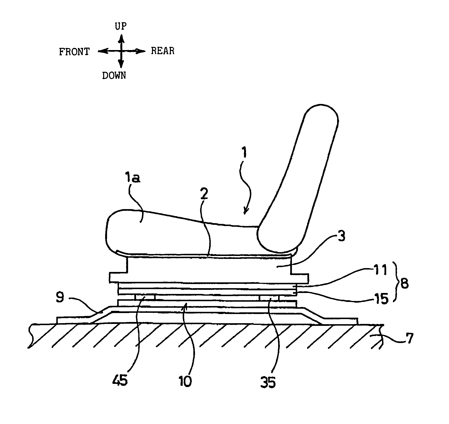
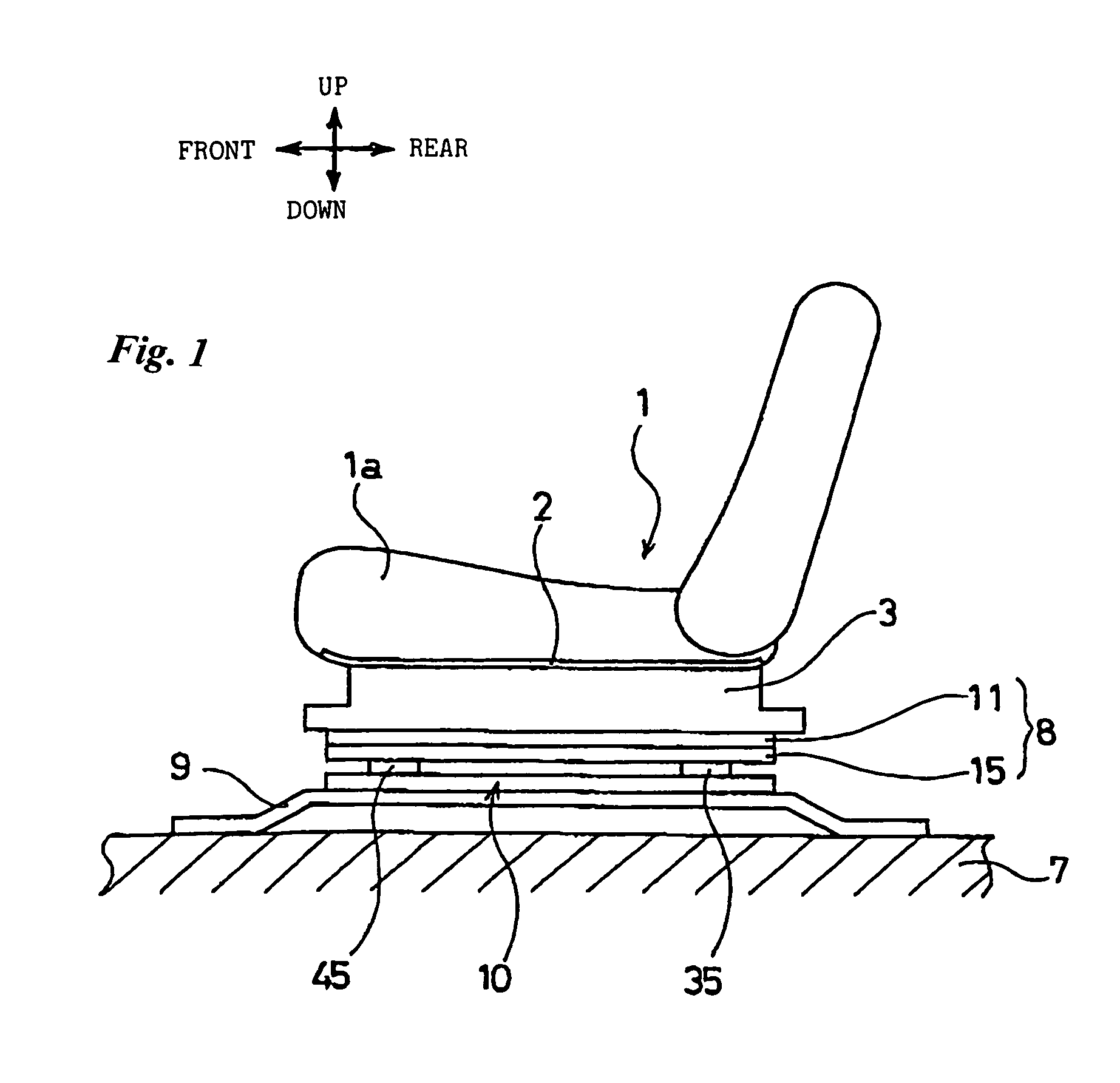
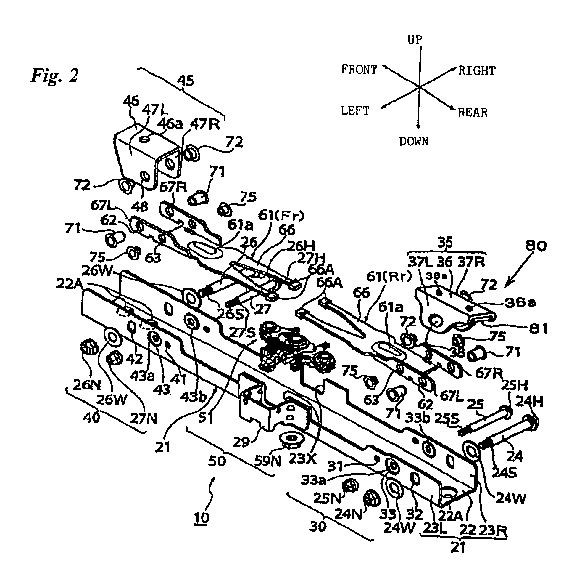
[0034]FIG. 1 is a side view of a vehicle seat to which an embodiment of a seat-load measuring apparatus according to the present invention is applied, FIG. 2 is an exploded perspective view of the embodiment of the seat-load measuring apparatus according to the present invention, FIG. 3(A) is a plan view of the seat-load measuring apparatus of this embodiment in an assembled state, FIG. 3(B) is a cross-sectional view, taken along line IIIB—IIIB in FIG. 3(A), FIG. 4 is an exploded perspective view of a sensor section in the seat-load measuring apparatus of this embodiment, and FIG. 5 is an enlarged partial view of the sensor section and its surroundings in the seat-load measuring apparatus of this embodiment. Throughout t...


PUM

PropertyMeasurementUnit
strengthaaaaaaaaaa
thicknessesaaaaaaaaaa
flexibilityaaaaaaaaaa

Abstract

A seat-load measuring apparatus includes: a base having an open top and configured to be fixed to a seat bracket configured to support a load imposed on a vehicle seat; an arm supported by the base and configured to receive the load imposed on the vehicle seat; a load sensor supported by the arm to detect the load imposed on the vehicle seat; a rail bracket configured to support a seat rail that movably guides the vehicle seat in a vehicle front-rear direction, and to connect the base to the seat rail; and a load support member connected to the rail bracket and configured to support a load imposed on the seat rail, the load being heavier than a predetermined load, where the base is connected under the seat rail with the rail bracket located between.

Description

BACKGROUND[0001]The present invention relates to a technical field of a seat-load measuring apparatus mounted under a seat rail for guiding a seat of a vehicle, such as a car, so as to measure the load imposed on the vehicle seat. More particularly, the present invention belongs to a technical field of a seat-load measuring apparatus having a connecting bracket that connects a base thereof to a seat rail.[0002]Seat-load measuring apparatuses 104 have been proposed which are mounted under seat rails 103 for guiding a vehicle seat 102, on which a person 101 sits, in order to measure the load imposed on the vehicle seat 102, as shown in FIGS. 14(A) to 14(C). In each seat-load measuring apparatus 104, a lower surface of a base 105 that has an upward-pointing angular-U shape in cross section is fixed to a seat mounting section 107 of a vehicle body with seat brackets 106 at the front and rear ends therebetween, and the seat rail 103 and the base 105 are connected by a pin bracket (herein...

Claims


Application Information

Patent Timeline
Patent Type & Authority Patents(United States)
IPC IPC(8): G01L1/26G01L5/04G01G23/02B60N2/00B60N2/90B60R21/01B60R21/015B60R21/02G01G19/12G01G19/414G01G19/52
CPCB60N2/002B60R21/01516G01G19/4142B60N2/0031B60N2210/42
Inventor KOBATA, TOSHIHIKOMOCHIZUKI, TETSUMEI
Owner HONDA MOTOR CO LTD
Learn More