
Software development process

a software development and process technology, applied in the field of software development process, can solve the problems of hardening linkage, difficult manipulation of locking modules together, and delivering flexible software, and achieve the effect of improving flexibility

Inactive Publication Date: 2006-02-14
WILDE TECH
View PDF4 Cites 146 Cited by
  • Summary
  • Abstract
  • Description
  • Claims
  • Application Information

AI Technical Summary

Benefits of technology

This approach enhances the flexibility of software systems by allowing for dynamic modification of component interactions and structure without requiring extensive code inspection or re-engineering, reducing costs and improving adaptability to changing requirements.

Problems solved by technology

The principal difficulty in delivering flexible software has long been known: strong couplings or bindings between code modules act to limit their viable independent usage, and lock the modules together in ways that are difficult to manipulate.
That these references are created and destroyed empirically, within functional code, in an intermingled fashion, further hardens the linkage.
This leads to high costs when restructuring interactions between tightly coupled modules.
Reuse and perhaps more importantly, changing a system's behaviour is not possible without inspection and modification of code, an expensive process.
However, these approaches provide limited flexibility because the components have a flat peer-to-peer structure which it is difficult to implement realistic system architectures.
However, the extent of flexibility is limited because this technology does not allow modification of interactions between components, without re-engineering at the code level.

Method used


Image

  • Software development process
  • Software development process
  • Software development process

Examples


Embodiment Construction

Brief Description of the Drawings

[0067]The invention will be more clearly understood from the following description of some embodiments thereof, given by way of example only with reference to the accompanying drawings in which:

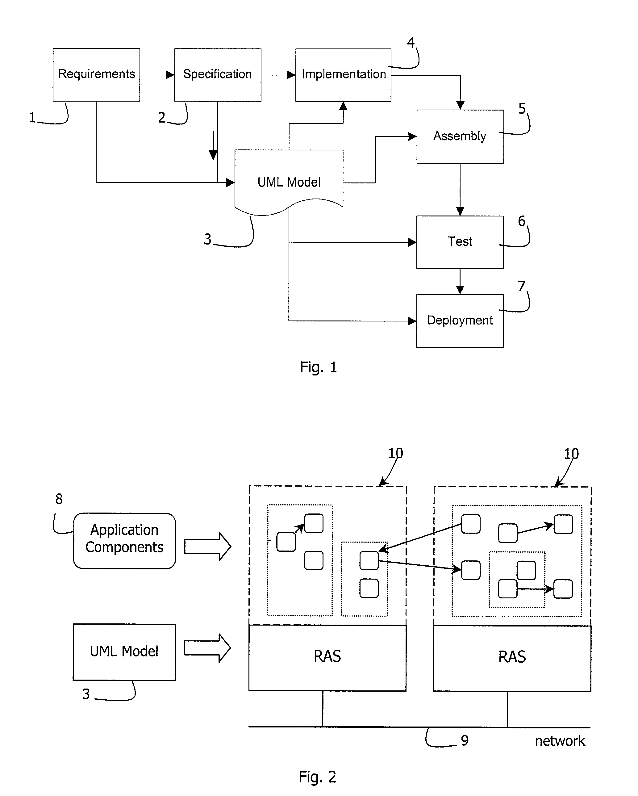
[0068]FIG. 1 is a high level diagram illustrating a software development process of the invention;

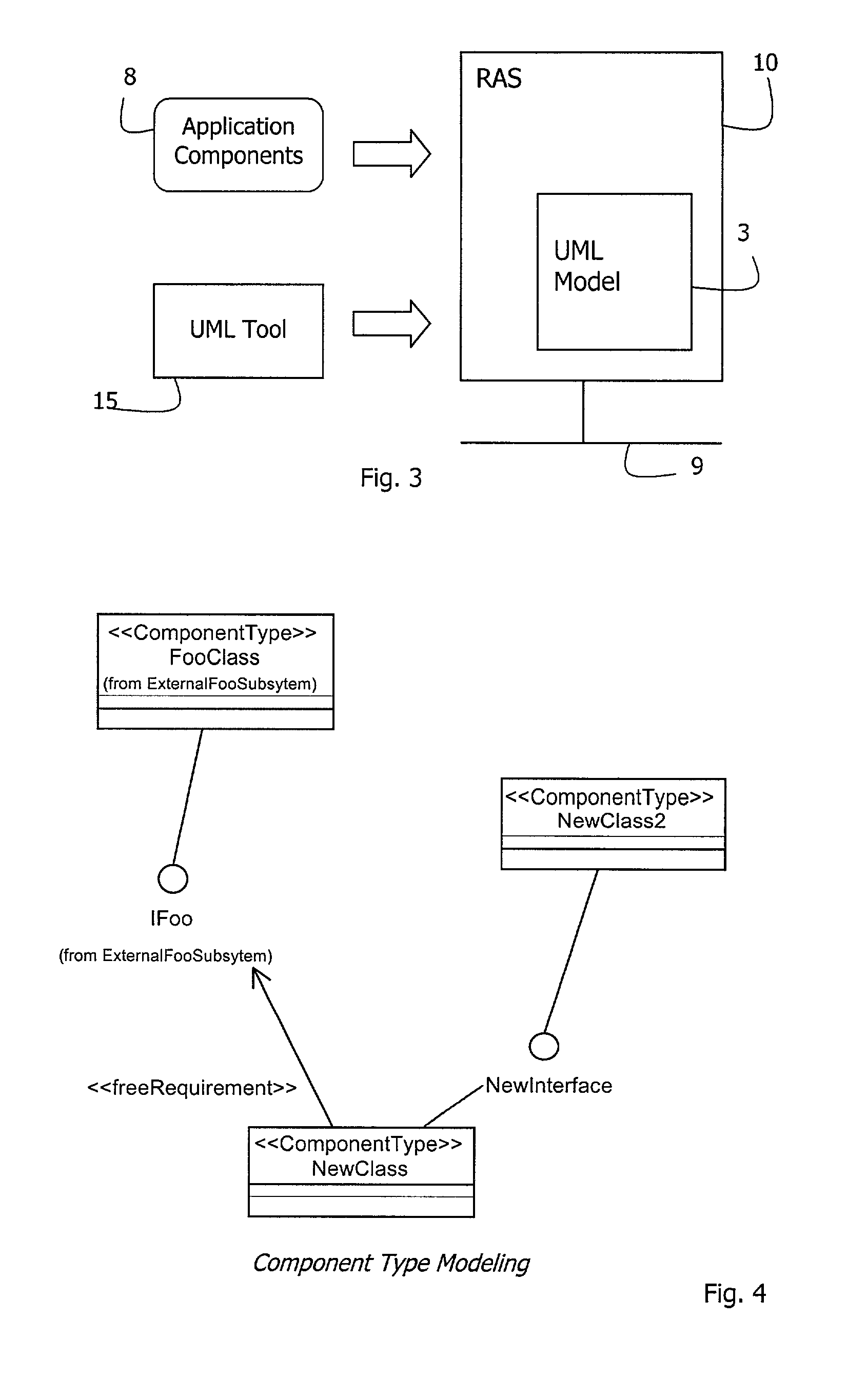
[0069]FIGS. 2 and 3 are diagrams showing execution of the system;

[0070]FIGS. 4, 5, and 6, are diagrams illustrating components and how they are modelled;

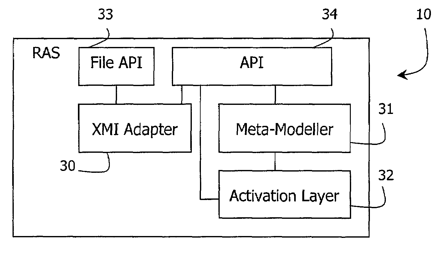
[0071]FIG. 7 is a diagram illustrating structure of a Runtime Architecture Service (RAS);

[0072]FIG. 8 is a class diagram of an XMI adapter of the RAS;

[0073]FIGS. 9 to 14 are class diagrams illustrating various aspects of the system;

[0074]FIGS. 15 to 20 are diagrams illustrating binding and unbinding of components.

DESCRIPTION OF THE EMBODIMENTS

[0075]FIG. 1 illustrates a development process as a set of development phases. In an iterative development process it may be assumed that these phases will occur in parallel ...


PUM


Abstract

A flexible component-based software system is developed by generating a UML model (3) in a specification phase (4). Components are generated in an implementation phase (4). The UML model (3) is transformed to a meta model. A runtime architecture service (RAS, 10) dynamically assembles a system in runtime according to the meta model. A modelling tool (15) modifies the meta model via an API (34) and a meta modeller (31). This allows dynamic re-configuration of the system.

Description

FIELD OF THE INVENTION[0001]The invention relates to a process for development of a flexible component-based software system, and to a system developed by such a process.PRIOR ART DISCUSSION[0002]A software system is generally regarded as “flexible” if it can undergo modification with relative ease in order to accommodate new requirements. This change may be effected via a restructuring of the interactions of its functional elements and / or the replacement of existing elements with alternates or via the addition or removal of elements.[0003]Flexibility is of benefit in a system which is required to operate in an environment which undergoes change. Not all systems are required to be flexible. However, in general, flexibility and the reduction of the cost of providing flexibility are often considered to be of benefit.[0004]The principal difficulty in delivering flexible software has long been known: strong couplings or bindings between code modules act to limit their viable independent...

Claims


Application Information

Patent Timeline
Patent Type & Authority Patents(United States)
IPC IPC(8): G06F9/45G06F8/20G06F9/44
CPCG06F8/24
Inventor BARRETT, STEPHENHIGGINS, COLUMTWOMEY, COLUMEVANS, MALCOLM
Owner WILDE TECH
Learn More