
Apparatus and method for decreasing stent gap size

a technology of stent gap and applicator, which is applied in the field of applicator and method for decreasing stent gap size, can solve the problems of substantial increase in manufacturing cost and possible materials problems, expansion ratio, coverage area, and strength that can ultimately be achieved, and achieve the effect of facilitating delivery, increasing vessel coverage, and maintaining the patency of the body lumen

Inactive Publication Date: 2006-02-14
ABBOTT CARDIOVASCULAR
View PDF15 Cites 40 Cited by
  • Summary
  • Abstract
  • Description
  • Claims
  • Application Information

AI Technical Summary

Benefits of technology

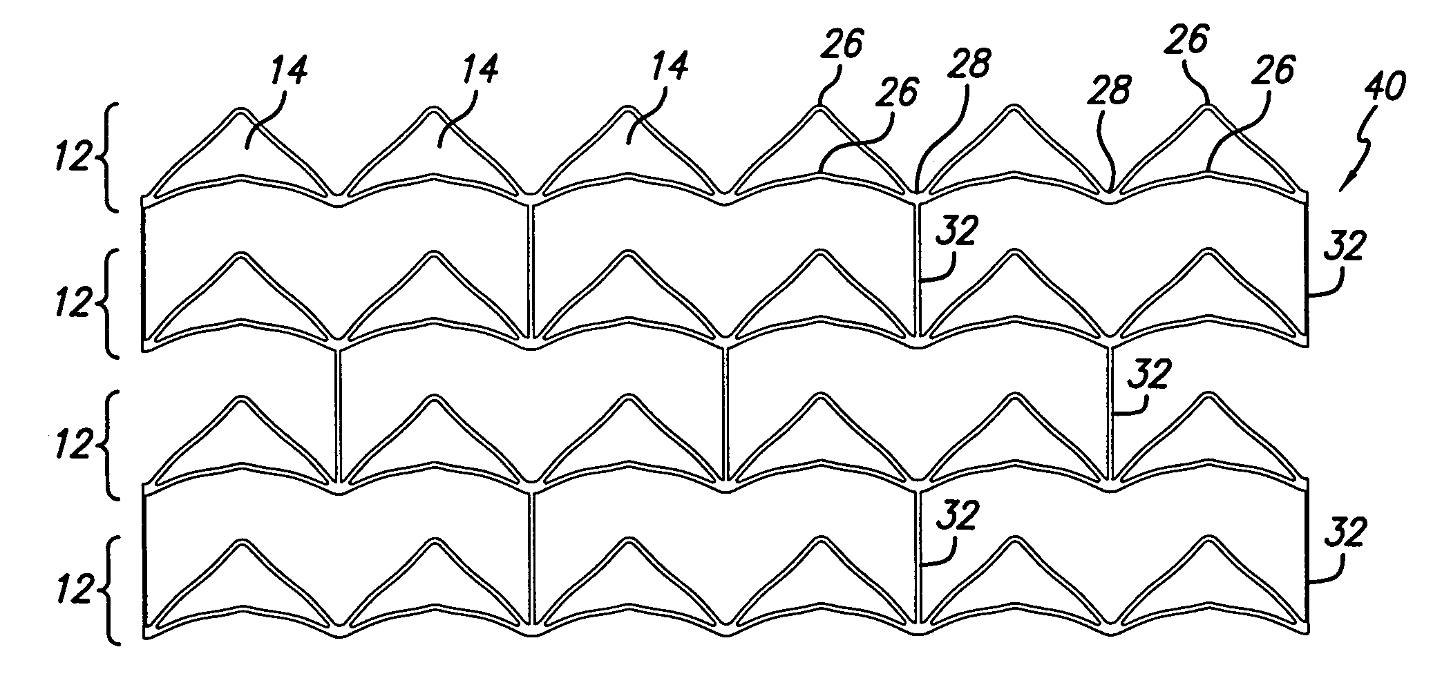
[0016]Accordingly, the present invention stent is relatively flexible along its longitudinal axis to facilitate delivery through tortuous body lumens, but is stiff and stable enough radially in an expanded condition to maintain the patency of a body lumen when implanted therein. Furthermore, the present invention stent by virtue of its double V strut pattern gives increased vessel coverage with reduced gap size thus decreasing the amount and likelihood of vessel wall or plaque prolapse without compromise to compressibility of the stent.

Problems solved by technology

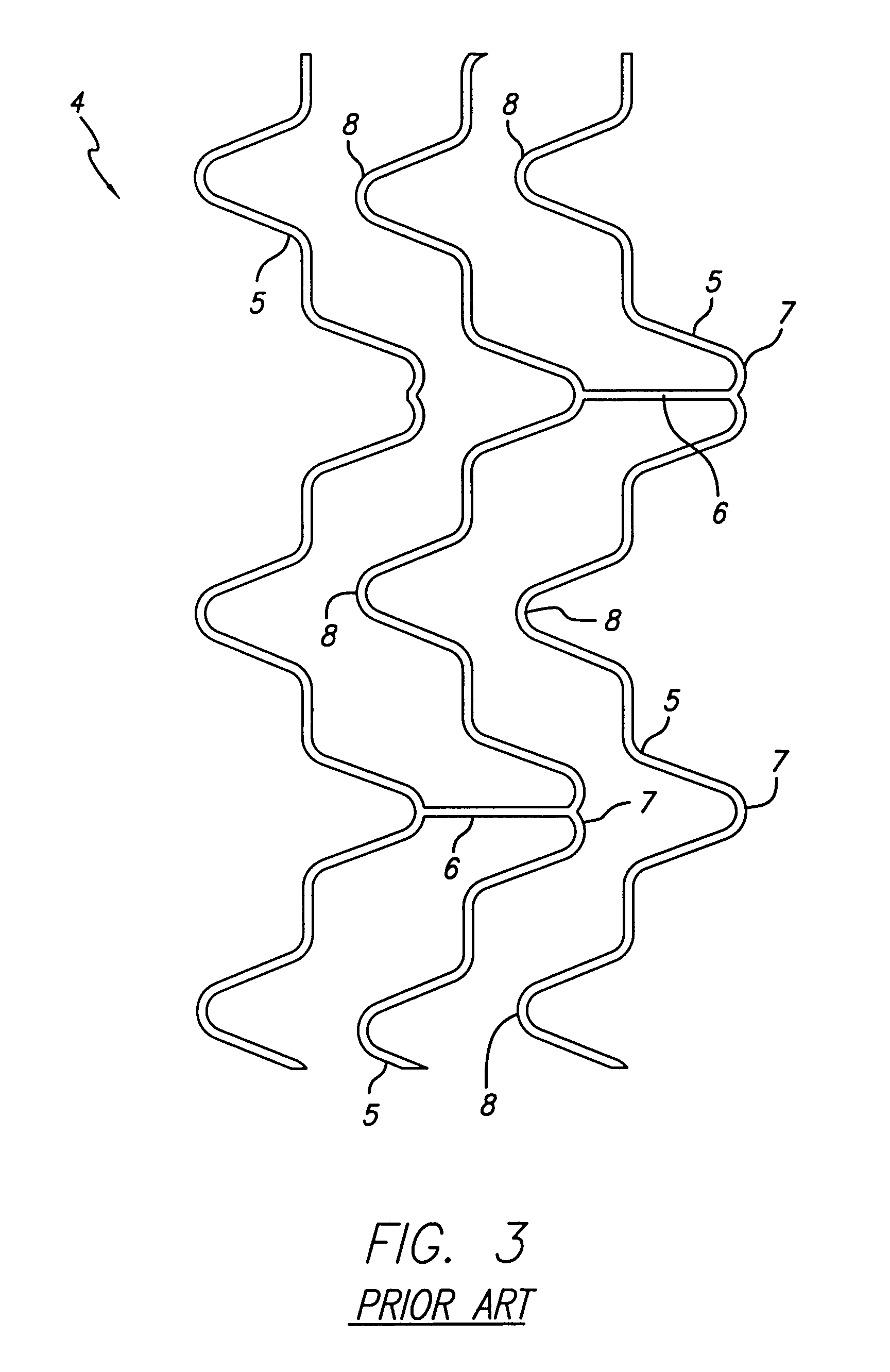
Additionally, wire has limitations with respect to the shapes it can be formed into thus impairing the expansion ratio, coverage area, and strength that can ultimately be attained.
Regarding strength, some have welded sections of wire together to increase strength albeit with a substantial increase in manufacturing costs and possible materials problems caused by welding heat.
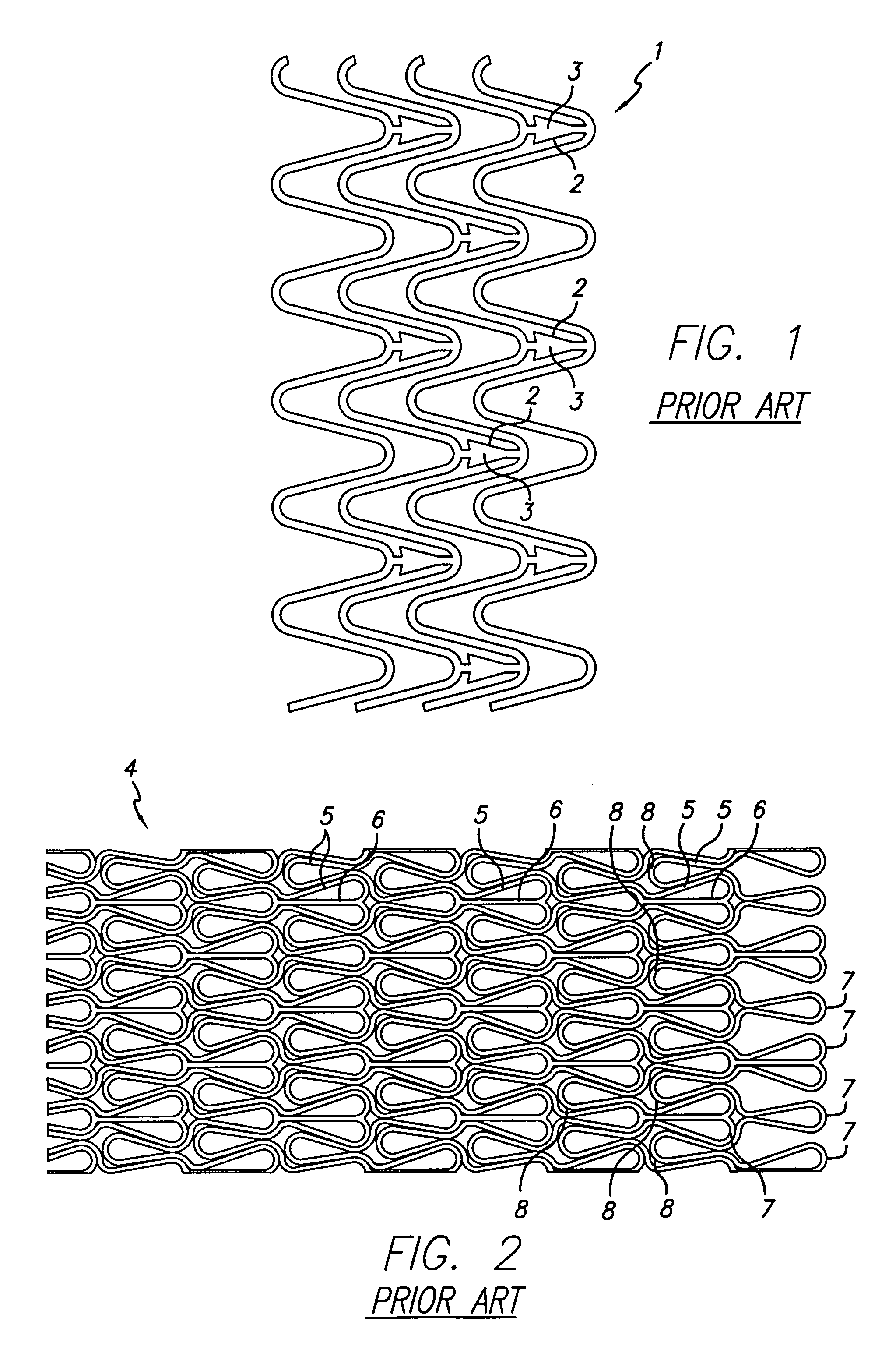
Yet a continuing obstacle encountered with prior art designs attempting to reduce the mass to space ratio is that as the mass to space ratio of the stent decreases, so does the vessel coverage provided by the same stent.

Method used


Image

  • Apparatus and method for decreasing stent gap size
  • Apparatus and method for decreasing stent gap size
  • Apparatus and method for decreasing stent gap size

Examples


Embodiment Construction

[0028]The present invention in a preferred embodiment is directed to an expandable stent that can be implanted in the body lumen. In a preferred embodiment, the stent has a plurality of rings aligned along a common longitudinal axis to form a tubular shape, wherein each ring includes a plurality of triangular cells and each cell includes at least two V struts having different amplitudes. The V struts are aligned in phase and joined at the opposite ends of the V struts to form the triangular shape cell. The stent further has one or more connecting elements joining the plurality of rings. Such a construction according to the present invention increases coverage by the stent, decreases the gap size between the struts, while allowing the stent to be compressed into a small profile for ease of deliverability.

[0029]FIG. 4 is a flattened plan view of a segment of the strut pattern for the present invention stent 10 in the compressed state. The stent 10 preferably has a plurality of rings 1...


PUM


Abstract

An expandable intraluminal stent having a strut pattern made from a plurality of triangular cells is disclosed. Each triangular cell is formed from at least two V struts of different magnitudes aligned in phase and joined at opposite ends forming two opposed vertices of the triangle. A series of triangular cells are joined at the vertices to form a ring. The series of triangular cells may be arranged to form peaks in the ring, peaks and valleys in the ring, or a combination thereof. A plurality of the rings are aligned coaxially and joined by connecting elements to form a tubular shape. Use of the double V strut formation in the rings increases vessel wall coverage, reduces gap sizes, and does not impair the compressability of the stent for a small profile for delivery.

Description

BACKGROUND OF THE INVENTION[0001]The present invention relates to expandable endoprosthetic devices, generally called stents, which are implanted in a patient's body lumen, such as blood vessel, to maintain the patency thereof. More particularly, the present invention relates to a triangular shape strut pattern for increased coverage and reduced gap size between the struts.[0002]Stents are generally tubular-shaped devices which function to hold open a segment of a diseased blood vessel or other anatomical lumen. For example, stents are useful in the treatment and repair of blood vessels after a stenosis has been compressed by a procedure such as percutaneous transluminal coronary angioplasty (PTCA), percutaneous transluminal angioplasty (PTA), or when the stenosis is removed by atherectomy or other means. They are also suitable for use to support and scaffold a dissected arterial lining that might occlude the fluid passageway or to repair an injured vessel wall as in an aneurysm.[00...

Claims


Application Information

Patent Timeline
Patent Type & Authority Patents(United States)
IPC IPC(8): A61F2/06A61F2/90
CPCA61F2/91A61F2/915A61F2002/91516A61F2230/0054A61F2002/91575A61F2002/91583A61F2002/91533
Inventor HARRISON, WILLIAM JAMESDENISON, ANDY E.
Owner ABBOTT CARDIOVASCULAR
Learn More