
Meniscus and soft tissue repair device and method of use

a meniscus and soft tissue technology, applied in the field of meniscus soft tissue repair devices and methods, can solve the problems of difficult operation, delicate procedure, pain and swelling, and catching sensation, and achieve the effect of convenient placement of one or more sutures and convenient operation

Inactive Publication Date: 2006-02-14
BITTAR EDWARD S
View PDF9 Cites 24 Cited by
  • Summary
  • Abstract
  • Description
  • Claims
  • Application Information

AI Technical Summary

Benefits of technology

[0010]With the present invention, however, there is provided a device that facilitates the placement of one or more sutures in the tissue of a patient and the device includes a main body that is a hollow tube that can be strategically located at the desired site where the suture is intended to pierce the tissue. The main body has a distal end that enters the joint or other area of the patient and that distal end is preferably configured to have a smooth rim so as to allow the entry into the patient to be introduced atraumatically. The main body also has a proximal end that has a slightly flared opening. The main body itself can be comprised of a metal, such as stainless steel, or can be a disposable material such as a plastic and it is preferred that the material be malleable so that the shape of the main body can be customized by the user by bending the main body to fit the desired use.
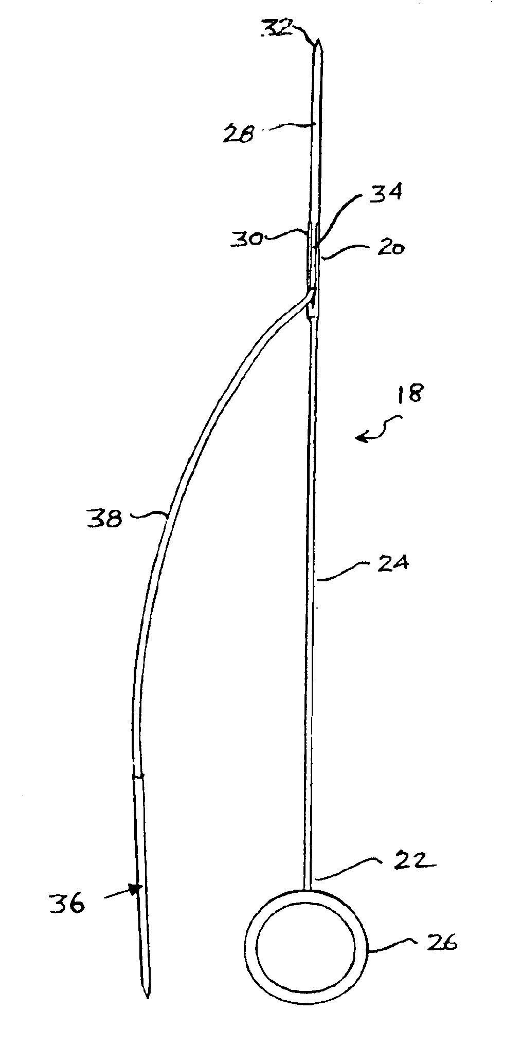
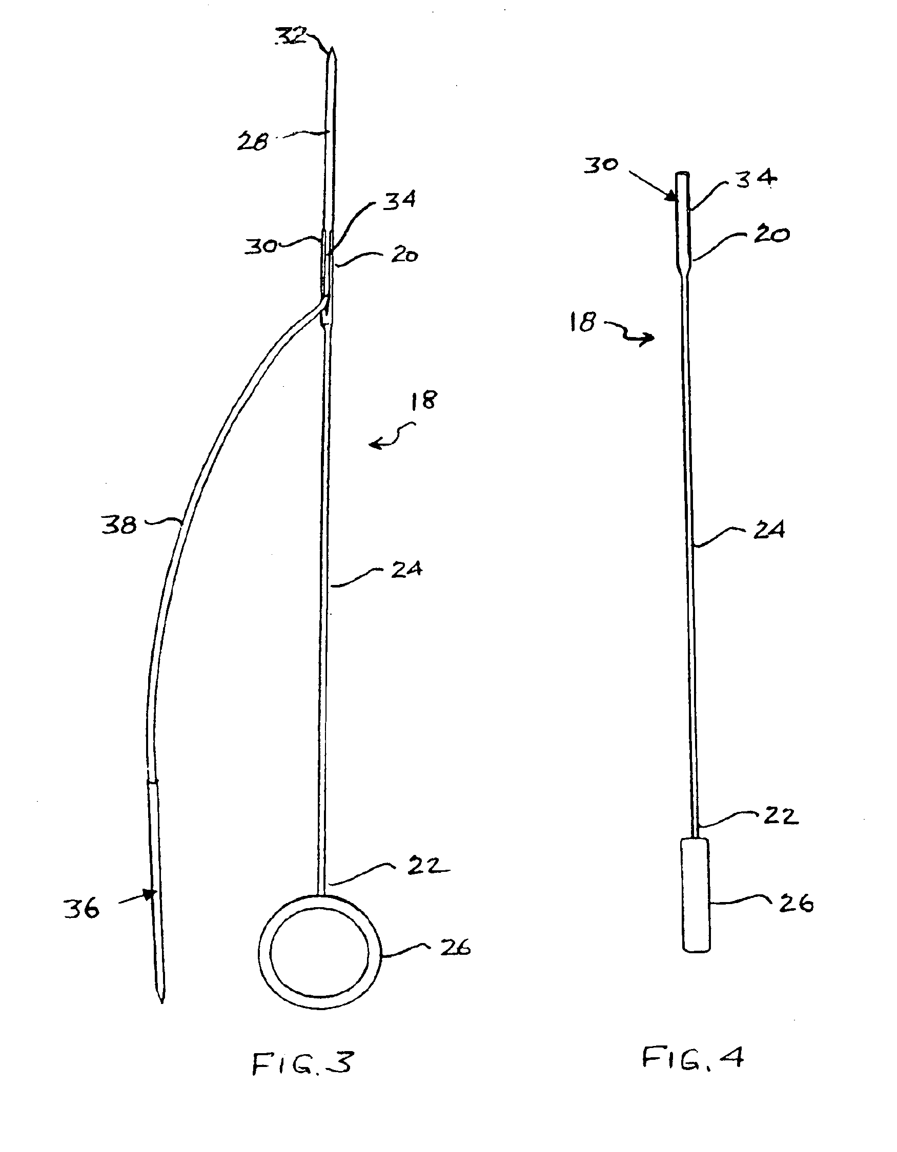
[0011]An introducer slidingly fits within the main body and the introducer has a distal end that has a socket to allow a needle to be frictionally interfitted therein and retained to that distal end. The socket also preferably has an elongated slit formed therein at least substantially along the length of the socket so as to allow a suture strand affixed to the needle to conveniently extend outwardly from the socket through the slit. As such, a needle having a suture strand affixed thereto can be fitted and retained onto the socket located at the distal end of the introducer and the introducer can be slid into and through the main body to a position where the distal end of the introducer projects outwardly from the distal end of the main body.
[0012]The introducer can be manipulated by some thumb securing means, such as a thumb ring, at the proximal end of the introducer so as to advance the needle to push the needle through the patient's tissue and across the tear in the meniscus and the needle pulled out the far end of the meniscus. In like manner, the proximal end of the main body also has finger securing means such as finger rings, that allow the fingers of the user's hand to hold the main body while advancing or retracting the introducer with the thumb ring. As can therefore be seen, the use of the device can be readily carried out with only one hand, making it particularly suitable for endoscopic surgical techniques.

Problems solved by technology

A rather common injury that can occur to the knee is a tearing of the meniscus and which can occur as a result, for example, of a twisting of the knee.
The tear can result in uneven surfaces that irritate the joint and can cause pain and swelling and a catching sensation.
Obviously, even with an arthroscopic instrument, the operation is a difficult, delicate procedure, requiring great skill since it requires the use of a suture or sutures that cross or span the tear and then a knot formed and tightened to bring the individual strands of the suture together so as to pull the separated sides of the tear together.
Thus a difficulty of the surgery is to be able to insert the needles carrying the suture and surgically position and insert the needles so as to pierce the meniscus to pass through the tissue of the meniscus as well as the tissue of the meniscus that has been torn apart in order to suture the torn portion back into the desired location.
Even with the use of the arthroscope, it is a delicate procedure to actually position the suture so as to pass the needles and the suture strand affixed thereto through the meniscus as well as the torn portion of the meniscus at two locations.

Method used


Image

  • Meniscus and soft tissue repair device and method of use
  • Meniscus and soft tissue repair device and method of use
  • Meniscus and soft tissue repair device and method of use

Examples


Embodiment Construction

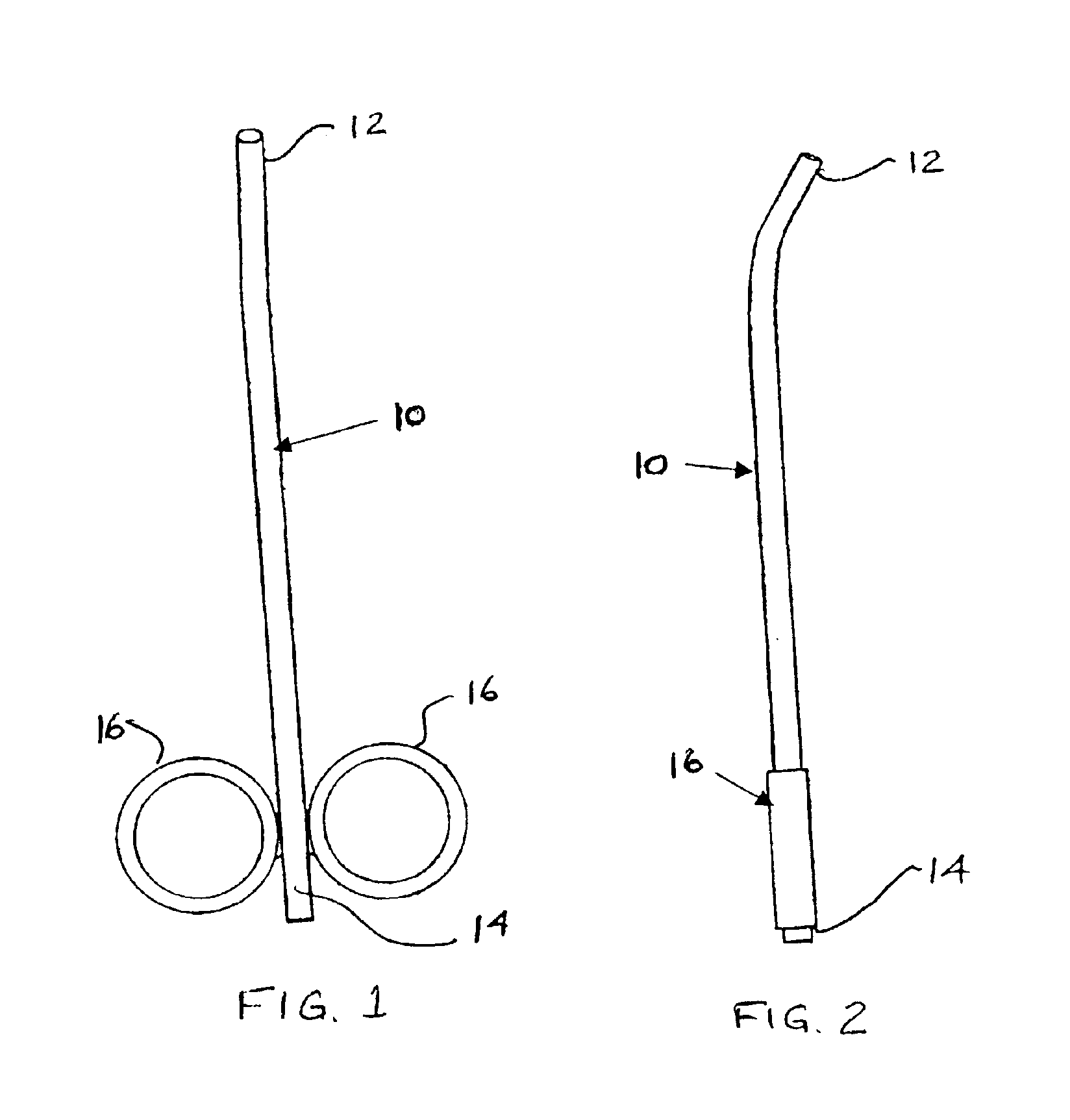
[0027]Referring now to FIGS. 1 and 2, there is shown a front view and a side view, respectively, of a meniscus and soft tissue repair device having a main body 10 that is basically a hollow tube with a lumen through the entire main body 10 and which is a component of the present invention. The main body 10 has a distal end 12 that is adapted to be inserted into the patient to be located proximate the area where a suture is to be inserted. As such, the distal end 12 has a smooth rim so that it can be introduced into the joint of the patient atraumatically.

[0028]There is also a proximal end 14 that may be slightly flared for a purpose that will later become clear. As also noted, at or near the distal end 12, the main body 10 is curved, however, the main body 10 may also be straight or differently curved in a variety of configurations. The material for the main body 10 can be a rigid material such as stainless steel or some malleable metal or a plastic, it being preferable that the mat...


PUM


Abstract

A device for repairing a meniscus or soft tissue. A needle having a suture strand attached thereto is affixed to the distal end of an introducer. The introducer is adapted to be inserted through a hollow main body to position the needle proximate a damaged portion of the meniscus. At the proximal ends of the introducer and main body, there is a thumb ring and a pair of finger rings that can be manipulated by the user to position the device and to pierce the meniscus with the needle. The needle is frictionally affixed to the introducer and can be removed by the user after piercing the meniscus and the outer skin of the patient. With the device, a pair of needles having a suture strand joining the needles can be inserted through the meniscus and across the damaged area and the strands of the suture affixed together.

Description

REFERENCE TO RELATED CASES[0001]The present application is based upon Provisional Application Ser. No. 60 / 375,338 filed Apr. 26, 2002 and entitled MENISCUS AND SOFT TISSUE REPAIR DEVICE AND METHOD OF USE.BACKGROUND OF THE INVENTION[0002]The present invention relates to a device for the repair of the soft tissue of a patient, and, more particularly, to a device and method to repair the meniscus of a knee of the patient.[0003]The meniscus is basically a crescent shaped fibrocartilage shock absorber that is located intermediate the femur or thigh bone and the tibia or shin bone and which assists in retaining the bones in place and includes an outside meniscus, that is, the lateral meniscus and the inside meniscus or medial meniscus. The meniscus, when healthy, absorbs the shock between the thigh bone and ankle bone by cushioning and distributing the forces across the joint as well as stabilizing the knee by controlling its rotation.[0004]A rather common injury that can occur to the kne...

Claims


Application Information

Patent Timeline
IPC IPC(8): A61B17/04A61B17/06A61B17/064
CPCA61B17/062A61B17/0643A61B2017/0646A61B2017/0472A61B2017/06057A61B2017/00946
Inventor BITTAR, EDWARD S.
Owner BITTAR EDWARD S
Learn More