Debris collection device and method

a collection device and a technology for debris, applied in the direction of rigid containers, packaging, borehole/well accessories, etc., can solve the problems of not being able to meet the needs of home, not being able to clean up after, and being unable to meet the needs of service installers

Inactive Publication Date: 2006-02-14
DUSTLESS DEPOT
View PDF39 Cites 13 Cited by
  • Summary
  • Abstract
  • Description
  • Claims
  • Application Information

AI Technical Summary

Benefits of technology

[0011]The first surface may include a number of tabs for use in pulling the first surface away from the second surface to thereby form the cavity. Preferably, the first surface includes two tabs, the tabs being on opposing sides of the through hole. The tabs may form

Problems solved by technology

Whilst in many industrial environments such debris would be unnoticeable, this is not the case in the home.
A related complaint is often raised against service installers (telecommunications and cable TV installers in particular) who drill many holes at a customers house to install their services, but rarely clean up after themselves.
Other than using sheeting to catch the majority of the debris, no simple and inexpensive mechanisms for controlling the spread of such debris is known to be available to small-scale installation operators or to the home DIY market.
Complex systems involving vacuums to suck away the dust have been developed over the years, but this usually requires additional vacuum pumps and ductin

Method used


Image

  • Debris collection device and method
  • Debris collection device and method
  • Debris collection device and method

Examples


Embodiment Construction

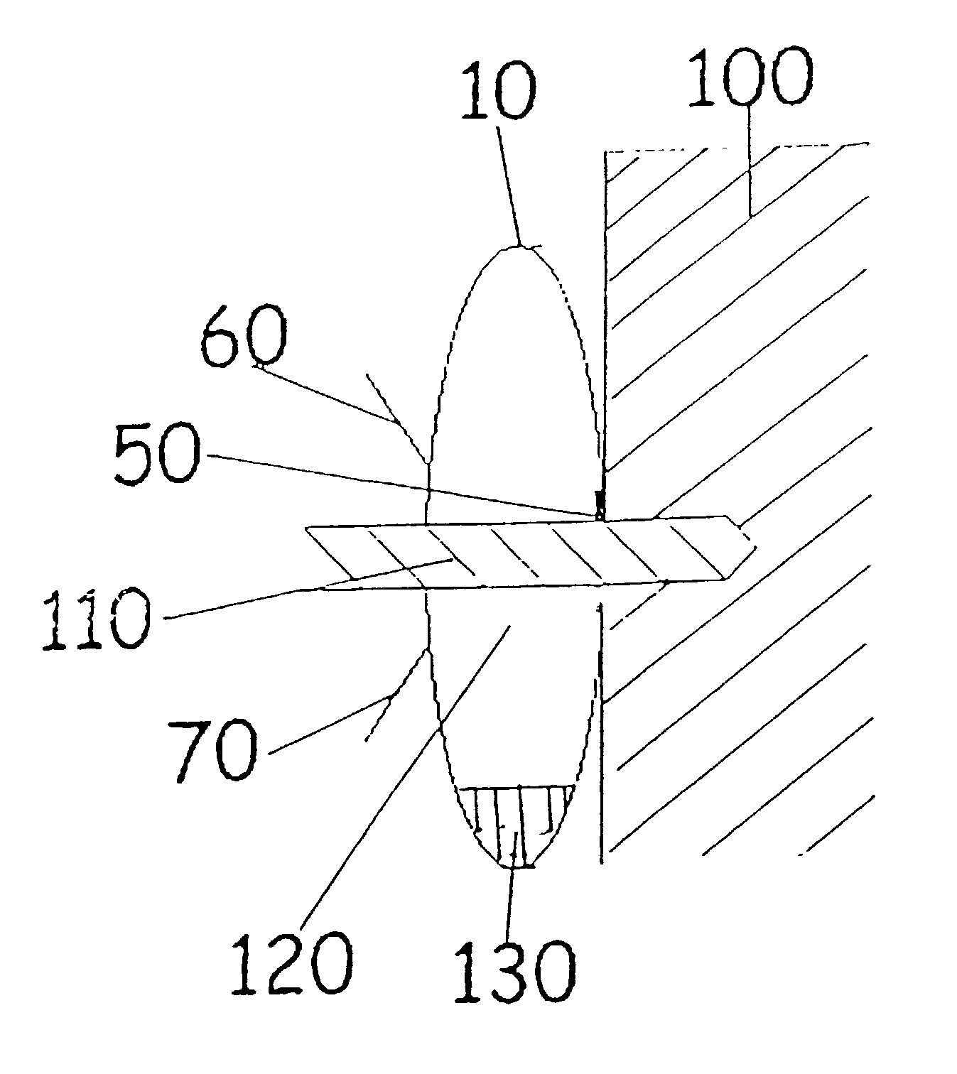
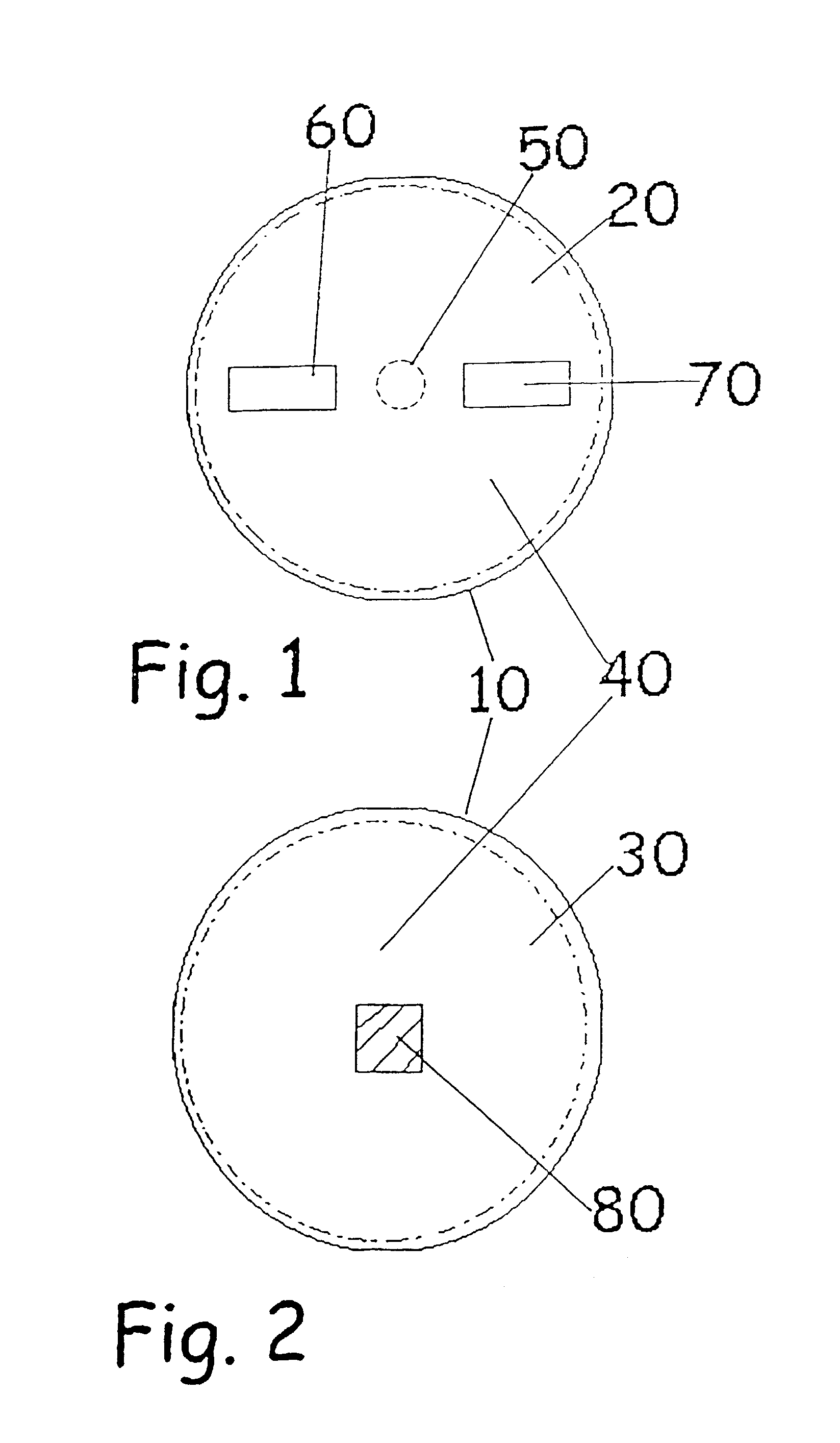
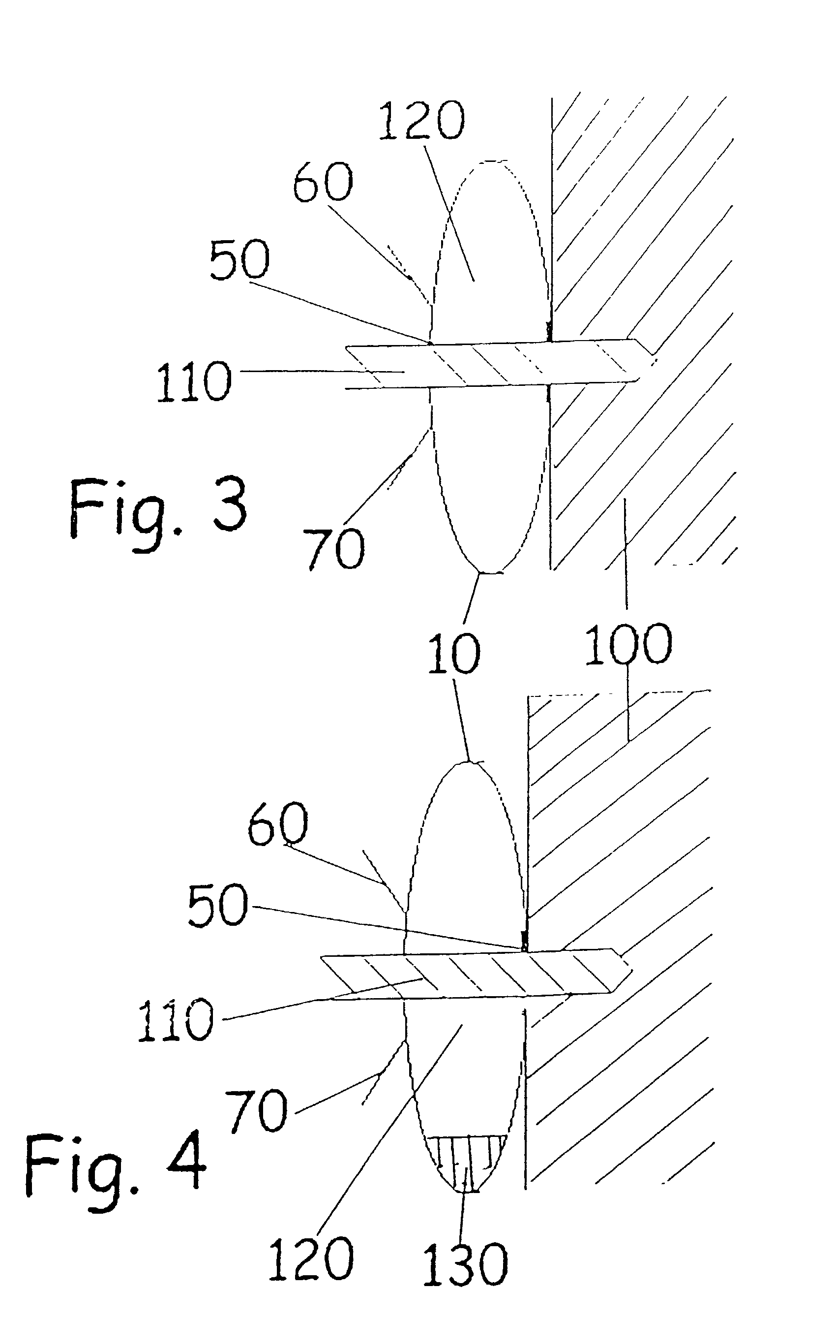
[0019]FIGS. 1 and 2 are, respectively, front and rear views of a collection device according to the present invention. The collection device comprises a body 10 having a front surface 20 and a back surface 30. The front and back surfaces 20, 30 are joined to each other around their perimeters (the joint is marked by a dash-dot line) to form an enclosed central area 40. The front surface 20 includes a through hole 50 capable of accepting a drill bit. The through hole 50 is preferably smaller or of the same diameter as the intended drill bit to be used. However, the size of the through hole is not essential to the operation of the device. In practice, a device with a 10 mm hole is used for all drill bits without adverse effect. Equally spaced either side of the through hole 50 are two tabs 60, 70 attached to the front surface 20. The back surface 30 includes an adhesive area 80 permitting adhesion of the body 10 to a surface.

[0020]FIG. 3 is a cross-sectional view of a collection devic...


PUM

PropertyMeasurementUnit
Flexibilityaaaaaaaaaa
Shapeaaaaaaaaaa
Adhesivityaaaaaaaaaa

Abstract

A collection device for use with a drill to capture debris ejected from drilling into a surface includes a body formed of flexible material having a first, substantially flat, configuration and a second erect configuration defining a cavity. The body includes a hole for receiving a drill bit into the cavity when the body is erect and adhesive means for adhering the body to the surface.

Description

FIELD OF THE INVENTION[0001]The present invention relates to a debris collection device for collecting dirt, debris and the like that is particularly useful when used in conjunction with rotary drills.BACKGROUND TO THE PRESENT INVENTION[0002]When drilling into surfaces using a standard rotary drill, the material drilled out of the surface is normally carried back along the length of the drill and scattered as granular dust or grit in the area directly below where the hole is being drilled. In some cases the quantity of debris generated by drilling a hole is particularly noticeable, for instance, a 10 mm hole at a 5 cm depth will create nearly 4 cm3 of debris that will be scattered about the immediate area, the majority forming a pile immediately below the hole. Whilst in many industrial environments such debris would be unnoticeable, this is not the case in the home. Particularly in the DIY environment, the house-proud occupant and / or their spouse are likely to require sheeting to b...

Claims


Application Information

Patent Timeline
IPC IPC(8): B23B47/34B23Q11/00
CPCB23Q11/0053B23Q11/0071Y10T408/50Y10T408/03Y10S206/813Y02P70/10B65F1/0013
Inventor STYLES, CHRISTOPHER
Owner DUSTLESS DEPOT
Why Eureka
Try Eureka