Piezoelectric element, piezoelectric actuator and liquid jetting head incorporating the same

a piezoelectric actuator and actuator technology, applied in the direction of positive displacement liquid engines, machines/engines, generators/motors, etc., can solve the problems of not being able to meet the recent-growing demand for piezoelectric elements and not being able to achieve the performance of multi-layer structures that are suitable for high-frequency driving

Inactive Publication Date: 2006-02-14
SEIKO EPSON CORP
View PDF21 Cites 14 Cited by
  • Summary
  • Abstract
  • Description
  • Claims
  • Application Information

AI Technical Summary

Benefits of technology

[0019]According to the above configurations, the degree to which the first common electrode is deformed by an electric field developing between the drive electrodes ...

Problems solved by technology

In this case, in order to ensure achievement of sufficient rigidity, a drive voltage must be increased, which is not suitable for high-frequ...

Method used


Image

  • Piezoelectric element, piezoelectric actuator and liquid jetting head incorporating the same
  • Piezoelectric element, piezoelectric actuator and liquid jetting head incorporating the same
  • Piezoelectric element, piezoelectric actuator and liquid jetting head incorporating the same

Examples


Embodiment Construction

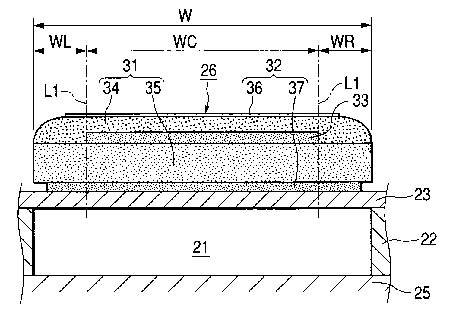
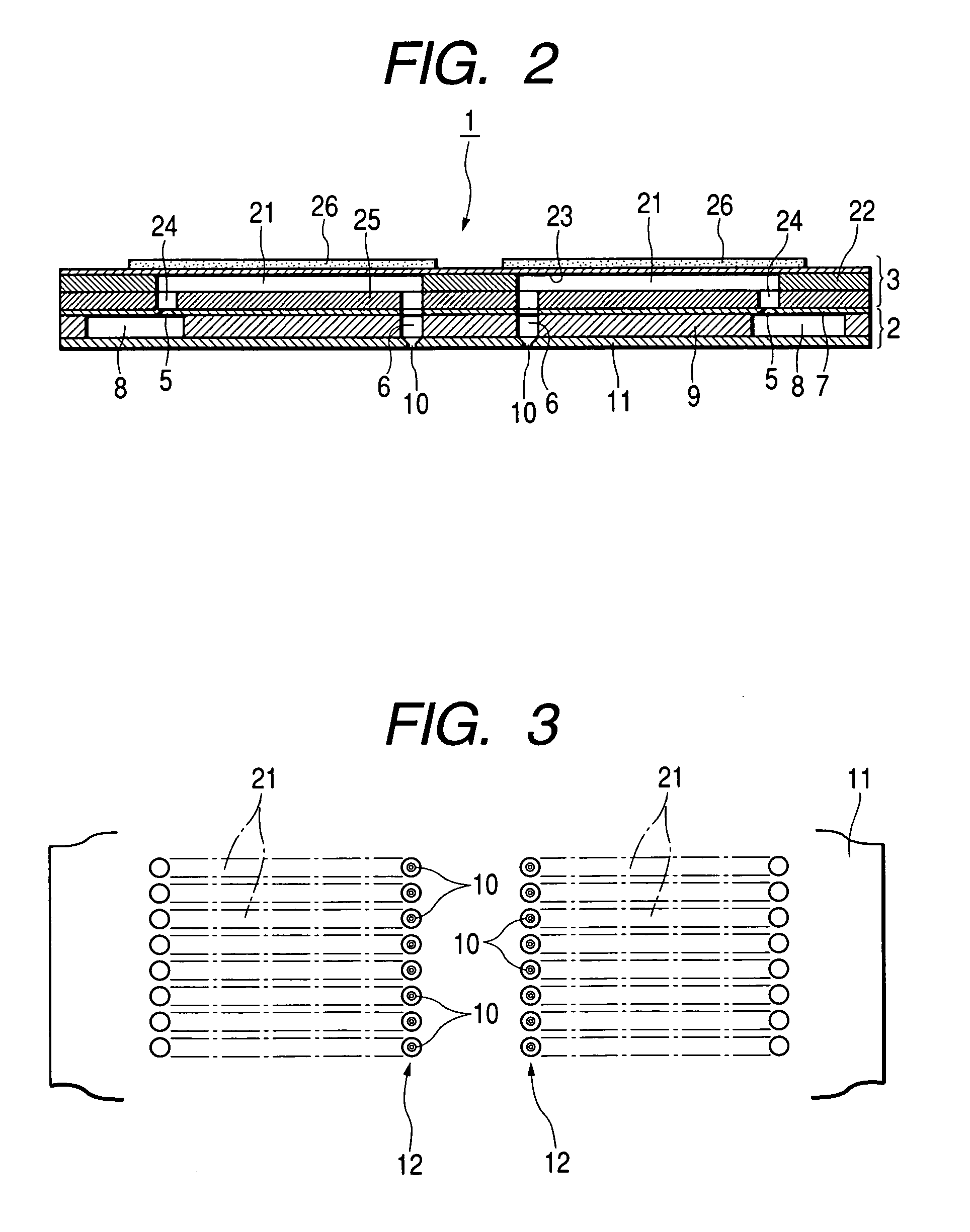
[0028]Embodiments of the invention will be described hereinbelow by reference to the accompanying drawings. Here, the embodiments will be described by taking, as an example, a recording head (a kind of liquid ejecting head) using a piezoelectric element. As shown in FIG. 1, a recording head 1 is essentially formed from a flow passage unit 2, a plurality of actuator units 3, and a film-shaped wiring board 4. The actuator units 3 are bonded side by side on the surface of the flow passage unit 2, and the wiring board 4 is attached to the surface of the actuator unit 3 opposite the flow passage unit 2.

[0029]As shown in FIG. 2, the flow passage unit 2 is fabricated from a supply port formation substrate 7 having formed therein through holes which are to serve as ink supply ports 5, and through holes which are to constitute portions of nozzle communication ports 6; an reservoir formation substrate 9 having formed therein through holes which are to serve as a common ink reservoir 8, and th...


PUM


Abstract

A first piezoelectric layer is laminated on a first common electrode and comprised of a first piezoelectric material having a first residual stress. A drive electrode is laminated on the first piezoelectric layer, to which a drive signal is supplied externally. A second piezoelectric layer is laminated on the drive electrode and comprised of a second piezoelectric material having a second residual stress lower than the first residual stress. A second common electrode is laminated on the second piezoelectric layer.

Description

BACKGROUND OF THE INVENTION[0001]The invention relates to a piezoelectric element which becomes deformed upon receipt of a supplied drive signal, to a piezoelectric actuator and a liquid ejecting head using such a piezoelectric element as a drive source.[0002]A piezoelectric element is formed from piezoelectric ceramics or a piezoelectric macromolecular film utilizing a high molecular compound and becomes deformed upon receipt of supplied electric energy, wherein the piezoelectric ceramics is formed by compressing and sintering metal oxide powder, such as BaTiO3, PbZrO3, PbTiO3, which are piezoelectric materials and exhibit a piezoelectric effect. The piezoelectric element is in widespread use as a drive element for, e.g., a liquid ejecting head, a micropump, and a sounding body (a speaker or the like). Here, the liquid ejecting head ejects a droplet from a nozzle orifice. The liquid ejecting head is embodied as, e.g., a recording head to be used in an image recording apparatus such...

Claims


Application Information

Patent Timeline
IPC IPC(8): B41J2/045B41J2/055B41J2/14F04B43/04H01L41/083H01L41/09H01L41/187
CPCH01L41/0973B41J2/14233H10N30/2047
Inventor JUNHUA, CHANG
Owner SEIKO EPSON CORP
Why Eureka
Try Eureka