
Semi-submersible offshore vessel and methods for positioning operation modules on said vessel

a technology of submerged offshore vessels and positioning operations, which is applied in the direction of waterborne vessels, special purpose vessels, floating buildings, etc., can solve the problems of reduced stability of the vessel, increased size of the vessel, and high center, and achieves low point of gravity, sufficient structural strength, and efficient and cost-effective effects

Active Publication Date: 2006-02-14
GVA CONSULTANTS
View PDF9 Cites 19 Cited by
  • Summary
  • Abstract
  • Description
  • Claims
  • Application Information

AI Technical Summary

Benefits of technology

"The present invention provides a semi-submersible offshore vessel that allows separate operational modules to be fitted in a cost-effective and efficient manner. The vessel has a C-shaped upper deck structure with a central module recess for receiving the operational modules, which can be fabricated separately from the vessel. The vessel has a low positioning of the operational modules, which results in a lower vertical center of gravity for the vessel. The invention offers these technical effects over conventional designs and allows for easy positioning and access of the operational modules."

Problems solved by technology

However, a disadvantage with this conventional design is that the operational modules have to be placed relatively high on the vessel which leads to a high center of gravity for the operational modules, and accordingly for the completed vessel.
This results in a reduction in stability for the vessel and as a consequence—a lesser pay-load, or alternatively the size of the vessel has to be increased to compensate for the high vertical center of gravity of the operational modules.
Furthermore, the weight and the size of these operational modules are normally such that there is only a limited number of devices available that can lift them, a fact that limits the number of available construction sites worldwide.

Method used


Image

  • Semi-submersible offshore vessel and methods for positioning operation modules on said vessel
  • Semi-submersible offshore vessel and methods for positioning operation modules on said vessel
  • Semi-submersible offshore vessel and methods for positioning operation modules on said vessel

Examples


Embodiment Construction

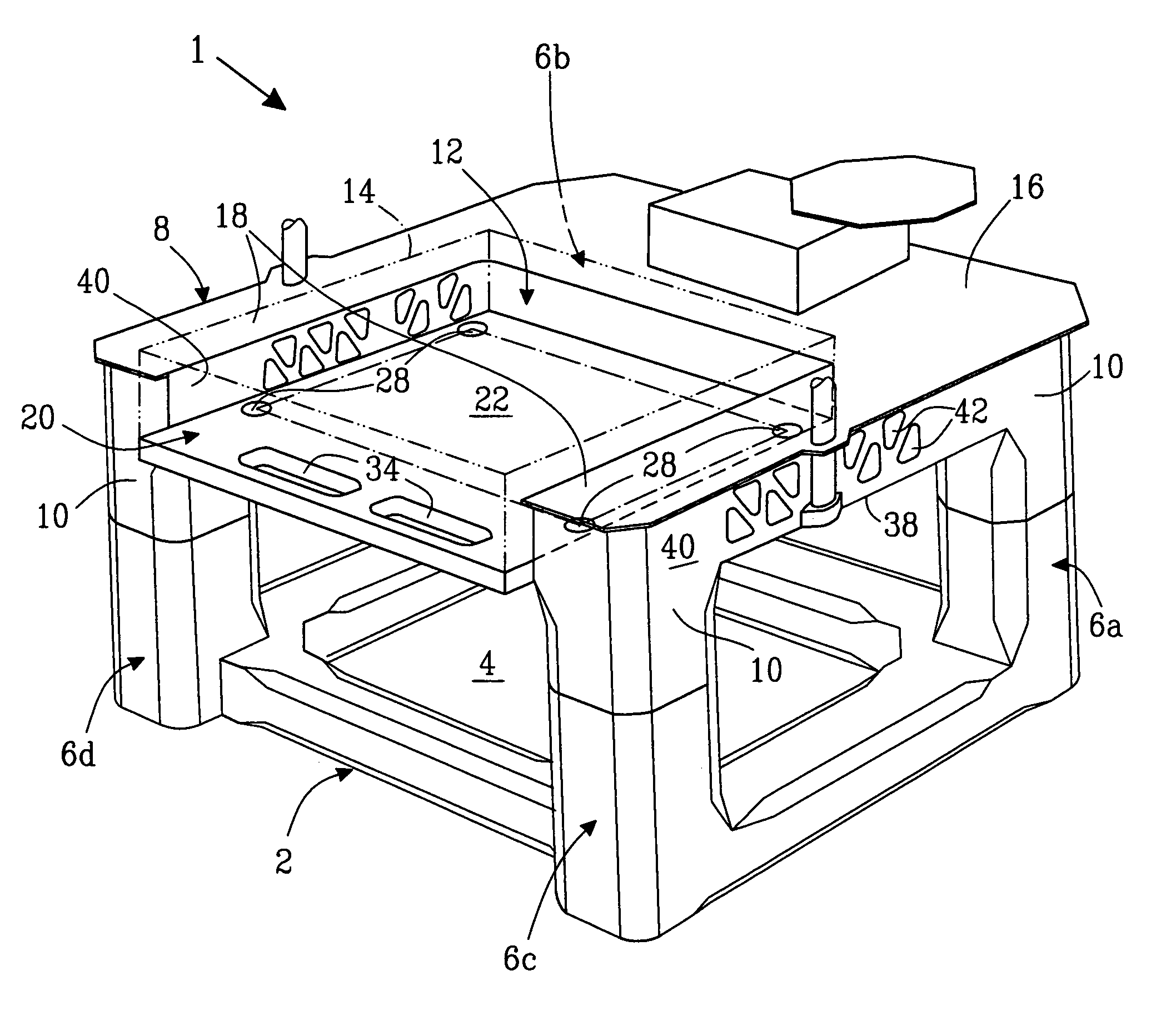
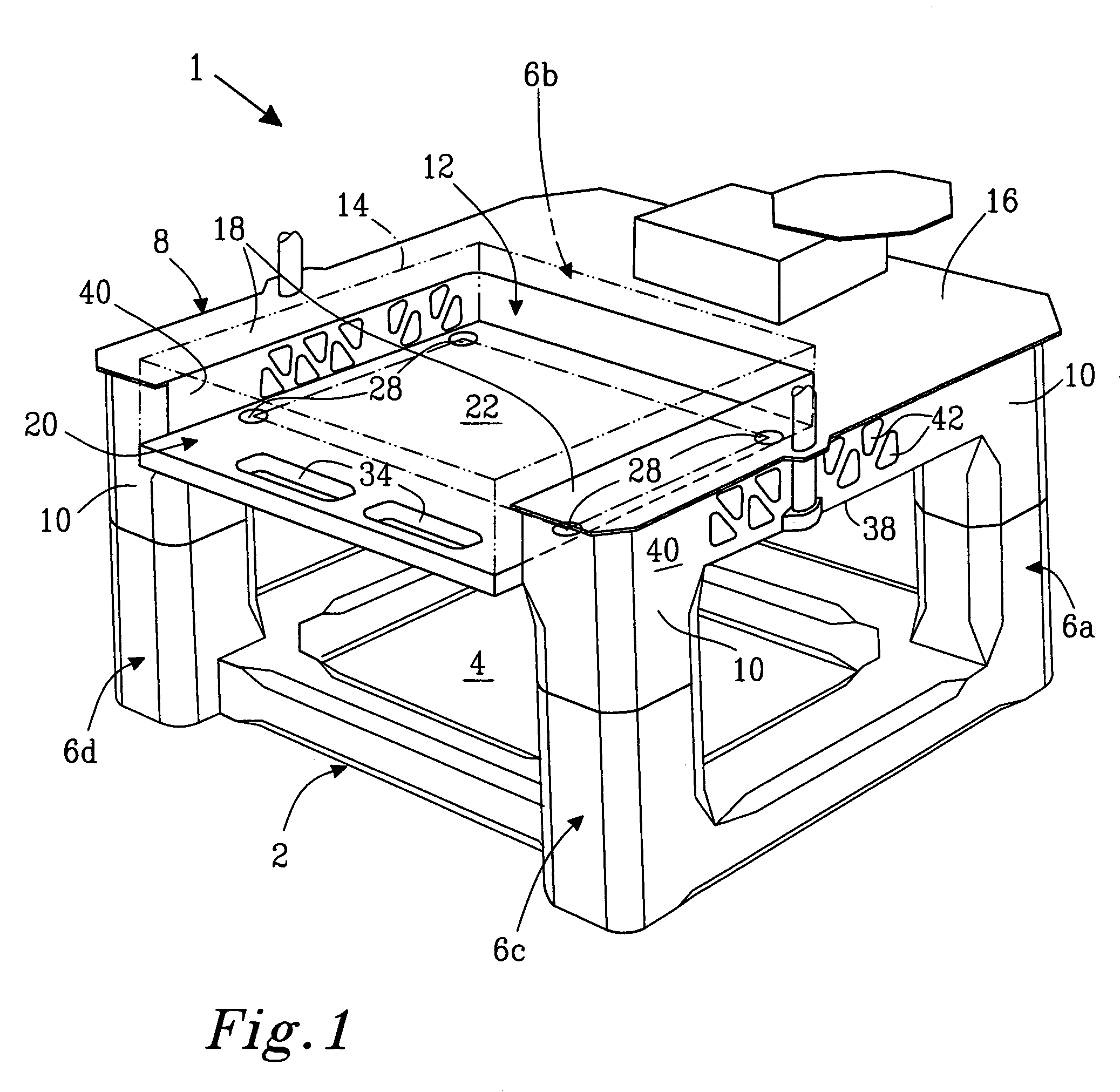
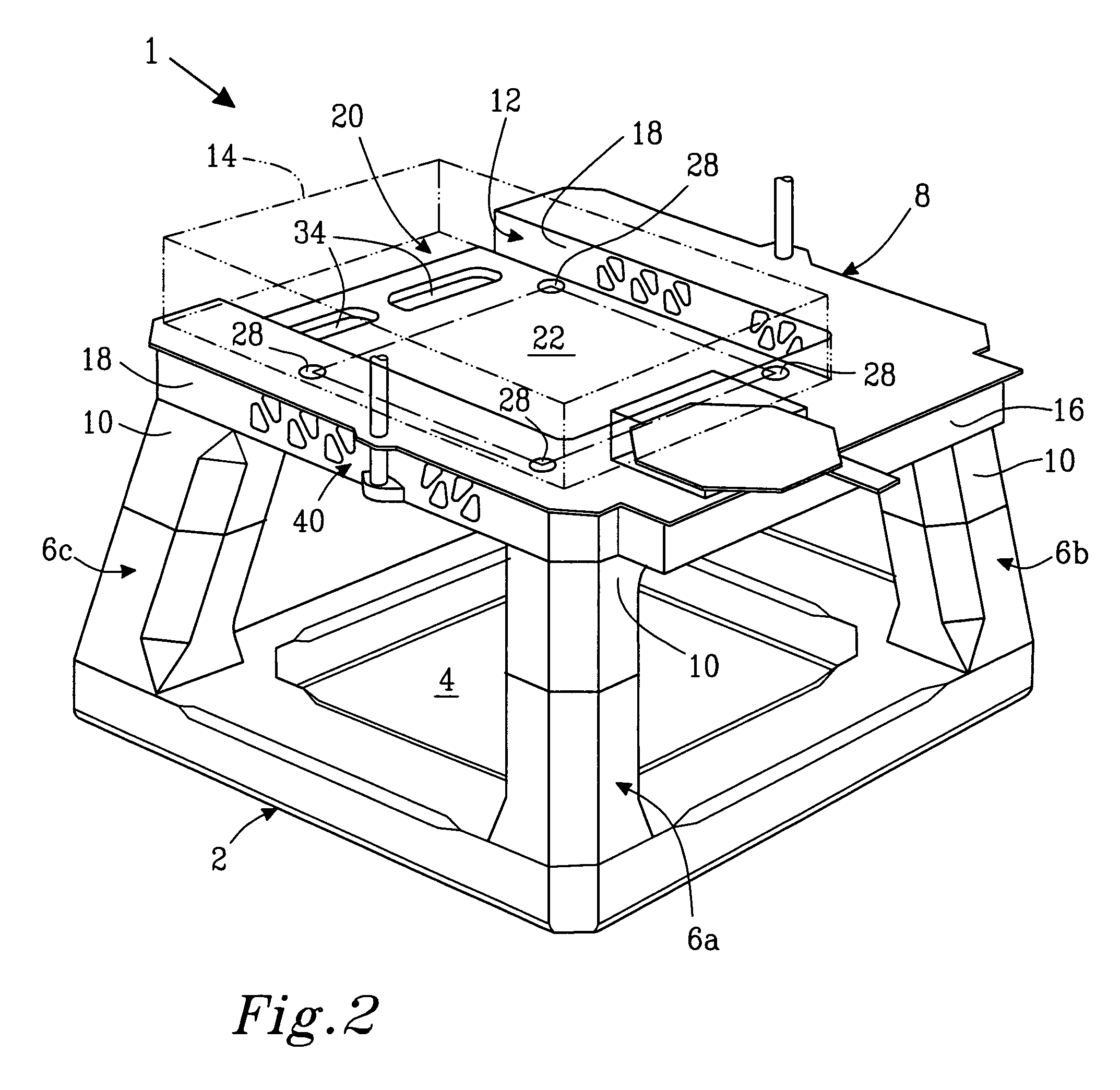
[0044]In FIG. 1, reference numeral 1 denotes a semi-submersible offshore vessel according to a first embodiment of the invention. The offshore vessel 1 is schematically illustrated without unnecessary detail and comprises a substantially rectangular, ring-shaped lower pontoon 2. The term “substantially ring-shaped” is used here in the meaning of a closed pontoon structure, which encloses a central opening 4. Such a pontoon structure is often popularly referred to simply as a “ring-pontoon”. Thus, the pontoon 2 shown in FIG. 1 is generally rectangular, whereas alternative embodiments may include other general pontoon shapes, such as polyhedral or circular pontoons 2 (not shown).

[0045]In the embodiment shown in FIG. 1, four columns 6a, 6b, 6c, 6d extend vertically upwards from the lower pontoon 2. More particularly, the vessel 1 has a starboard forward column 6a, a port forward column 6b (hidden in FIG. 1), a starboard aft column 6c and finally a port aft column 6d. In the shown embod...


PUM


Abstract

A semi-submersible offshore vessel has a substantially ring-shaped lower pontoon, starboard and port forward columns extending upwards from the lower pontoon, and starboard and port aft columns extending upwards from the lower pontoon. An upper deck structure connects upper portions of the columns with each other. The upper deck structure has a substantially rectangular module recess for receiving one or more operation modules, for example, carrying hydrocarbon-processing equipment. The upper deck structure is generally C-shaped, having a forward torsion box extending transversally between the starboard and the port forward columns of the semi-submersible offshore vessel, and two mutually parallel longitudinal side beams extending aft from the starboard and port forward columns to the starboard and port aft columns, respectively, in such a way that the module recess exhibits an open aft end, the width of which substantially corresponds to the width of an operation module. The module recess is delimited in a downward direction by a substantially planar module deck, which extends between and interconnects the longitudinal side beams.

Description

[0001]This Non-provisional application claims priority under 35 U.S.C. § 119(a) on Patent Application No(s). 0400909-8 filed in Sweden on Apr. 2, 2004, the entire contents of which are hereby incorporated by reference.TECHNICAL FIELD[0002]The present invention relates to a semi-submersible offshore vessel comprising a substantially ring-shaped lower pontoon, at least four columns extending upwards from said lower pontoon, and an upper beam structure connecting upper portions of the columns with each other. The offshore vessel is especially designed to be fitted with one or more operation modules, for example carrying hydrocarbon processing equipment. The invention also discloses methods for positioning operation modules on said vessel.BACKGROUND[0003]In conventional semi-submersible vessels, a load-supporting, rectangular deck-box structure is positioned upon the top of the columns. Operation modules are then placed on top of the deck-box structure. The deck-box structure offers a s...

Claims


Application Information

Patent Timeline
Patent Type & Authority Patents(United States)
IPC IPC(8): B63B35/44B63B
CPCB63B35/4413
Inventor STEEN, GERRY
Owner GVA CONSULTANTS
Learn More