
AutoSolar Thermal Electric Conversion (ASTEC) solar power system

a solar power system and solar thermal technology, applied in the direction of machine/engine, steam generation using solar heat, transportation and packaging, etc., can solve the problems of inability to provide low-cost power to the consumers of this or any other nation, inherently so expensive, and all are utterly incapable of competing economically with conventional power plants and heat-power systems. achieve the effect of high efficiency, advanced technical performance and cheap production

Inactive Publication Date: 2006-02-14
EMC2
View PDF7 Cites 59 Cited by
  • Summary
  • Abstract
  • Description
  • Claims
  • Application Information

AI Technical Summary

Benefits of technology

[0004]In accordance with principles of embodiments of the invention, solar power can be made inexpensively, but not with high-tech R&D products, but rather by use of proven, reliable heat-power equipment and devices which are mass-manufactured in the tens of millions by the US automotive, air conditioning and refrigeration industries. This approach abandons the scientist's desire for high efficiency and advanced technical performance, in favor of the investment community's criterion of product low-cost and high rate-f-return on investment.
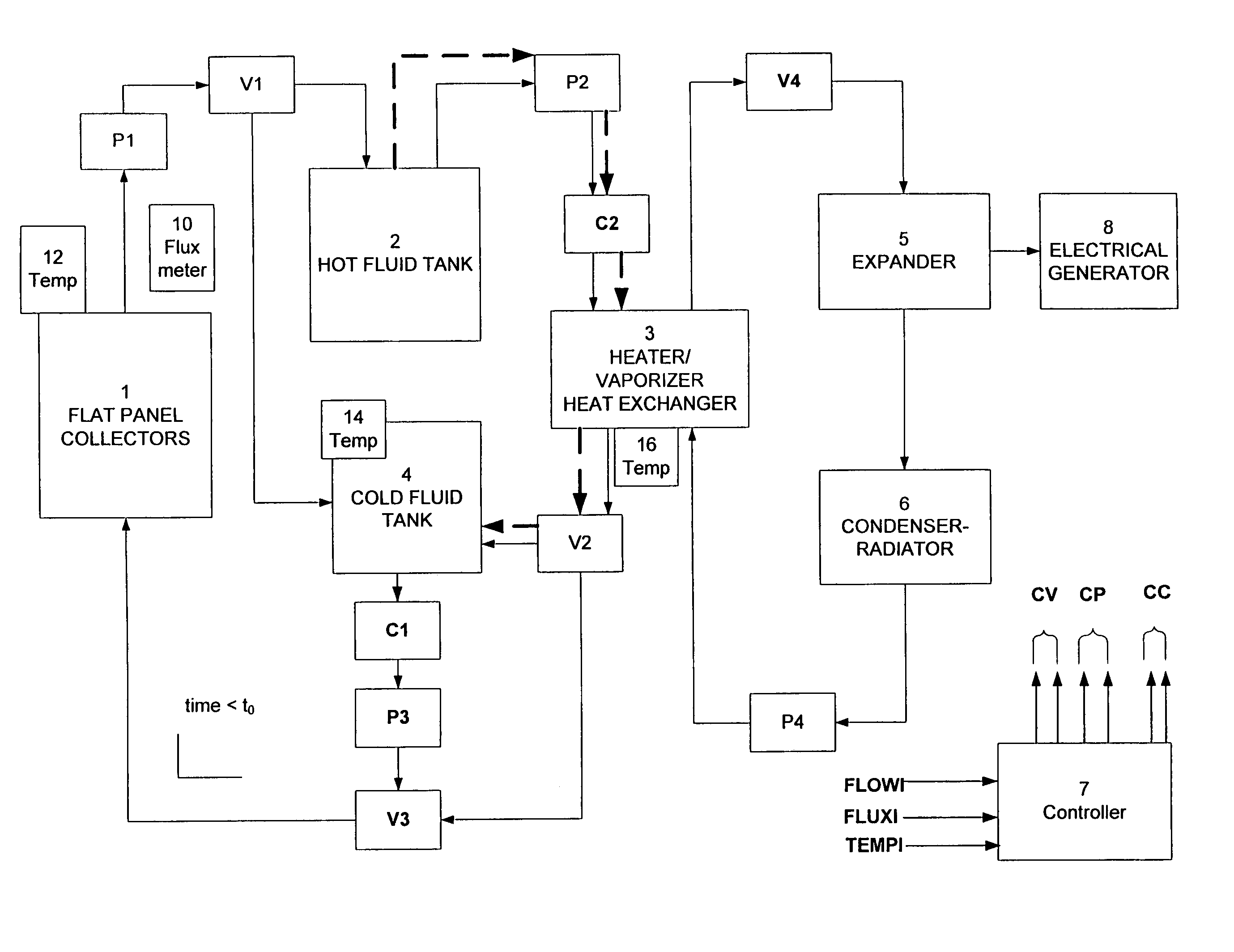
[0008]Collectors are fabricated at low cost from the mass-manufactured back plates which reject heat in (older) conventional refrigeration systems. These form the main collection elements in the complete collector unit, which uses double pane thin-glass covers, modest back insulation and mounting in a low-cost wood frame box. The fluid to be used in the collector plates may be either water or a standard heat transfer oil (e.g. Dowtherm A). Thermal energy storage, to allow system power generation during dark time (night), can be provided at very low cost by use of the cooling fluid (e.g. water) stored in a simple insulated tank, which supplies heated fluid to the Rankine cycle fluid heater radiators.

Problems solved by technology

All have been inherently so expensive that they have been cost-supported by tax relief schemes or rebates, and all are utterly unable to compete economically with conventional power plants and heat-power systems.
The result of these billions of dollars of R&D is that these solar power systems can NOT provide low-cost power to the consumers of this or any other Nation.
This failure of solar power R&D to yield useful systems is precisely because it was conducted as R&D, not as construction of systems from available low-cost heat-power machinery.
The excessive cost of all past solar power systems is a direct result of this struggle to develop and employ equipment and systems of advanced high technical performance.

Method used


Image

  • AutoSolar Thermal Electric Conversion (ASTEC) solar power system
  • AutoSolar Thermal Electric Conversion (ASTEC) solar power system
  • AutoSolar Thermal Electric Conversion (ASTEC) solar power system

Examples


Embodiment Construction

Solar Insolation, Absorption and Capture Efficiency

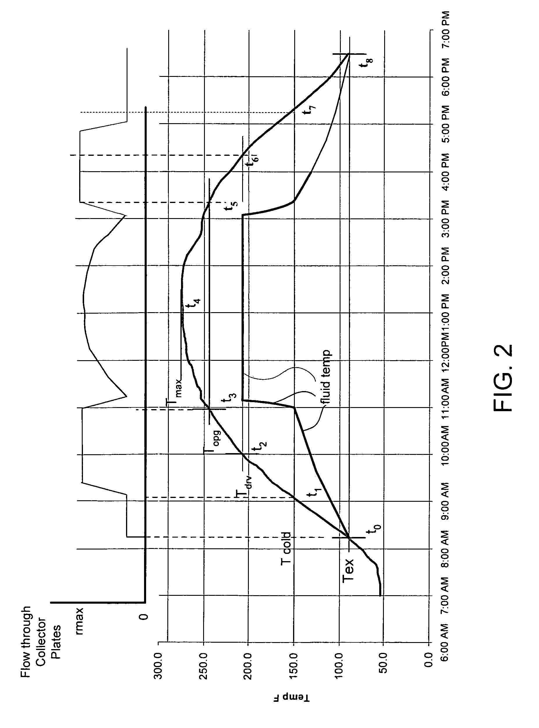
[0026]Data have been taken over many years for solar insolation in the US. It has been found that areas with the highest solar flux / fluence are in the Southwest, including Southern California, Arizona, New. Mexico and parts of Texas. Here, measurements show that the total solar energy fluence (Fo) incident on a surface perpendicular (normal) to the sun during the daylight hours (requires turning the incident surface to make this measurement) varies from about F0=10 kWthhrs / m2 in the summer (June) months to F0=5 k Wthhrs / m2 in the winter (December). For design purposes for the ASTEC system solar power system, the average normal summer insolation has been taken as Fos=9.6 kWthhr / rn2 and that in the winter as Fow=4.8 kWthhr / m2.

[0027]Realistic economic considerations make tracking collectors impractical, as the increased collection achieved is generally not worth the considerable cost of the tracking and mounting systems, flexible pipin...


PUM


Abstract

A thermal collection system has a first tank for storing relatively hot working fluid and a second tank for storing relatively cold working fluid. A heat exchanger is connected for receiving the relatively hot working fluid from the first tank for providing heat to the heat exchanger. The heat exchanger discharges the working fluid at a lower temperature than a temperature of the relatively hot working fluid of the first tank. A solar panel collector is connected for receiving the lower temperature working fluid from the heat exchanger and for heating the lower temperature working fluid and feeding same to a first control valve. The first control valve is operative for feeding working fluid from the solar collector selectively to one of the first tank and the second tank. The second tank has a second control valve selectively operative for permitting working fluid from the second tank to flow to the solar collector. Improved collection efficiencies in the solar collector may be obtained using the two tank structure for passing working fluid through the solar collector.

Description

CROSS REFERENCE TO RELATED APPLICATION[0001]This application claims benefit under 37 C.F.R. §119 (e) of U.S. provisional Application Ser. No. 60 / 443,296 filed Jan. 28, 2003, the entire contents of which is incorporated herein by reference.BACKGROUND OF THE INVENTION[0002]Billions of dollars have been spent in solar energy R&D, and tens of thousands of solar energy devices and systems have been built, sold, and installed across the US. All have been inherently so expensive that they have been cost-supported by tax relief schemes or rebates, and all are utterly unable to compete economically with conventional power plants and heat-power systems. The result of these billions of dollars of R&D is that these solar power systems can NOT provide low-cost power to the consumers of this or any other Nation.[0003]This failure of solar power R&D to yield useful systems is precisely because it was conducted as R&D, not as construction of systems from available low-cost heat-power machinery. The...

Claims


Application Information

Patent Timeline
IPC IPC(8): B60K16/00
CPCF01K3/12F22B1/006F01K25/08
Inventor BUSSARD, ROBERT W.
Owner EMC2
Learn More