Potential energy storage system

a technology of power storage and potential energy, applied in the direction of shock prevention, machines/engines, transportation and packaging, etc., can solve the problems of limited lifetime and/or generation capacity, inefficientness, and high cost of existing systems, so as to optimize efficiency and power generation, minimize or limit relative lateral movement of buildings, and maintain vertical stability

Inactive Publication Date: 2006-02-14
HALLORAN JOHN J
View PDF28 Cites 27 Cited by
  • Summary
  • Abstract
  • Description
  • Claims
  • Application Information

AI Technical Summary

Problems solved by technology

Existing methods of electrical power generation used to provide alternative or backup power sources to established energy grid systems have various difficulties associated with them.
These existing systems are often expensive, inefficient, have a limited lifetime and / or generation capacity.

Method used


Image

  • Potential energy storage system
  • Potential energy storage system
  • Potential energy storage system

Examples


Embodiment Construction

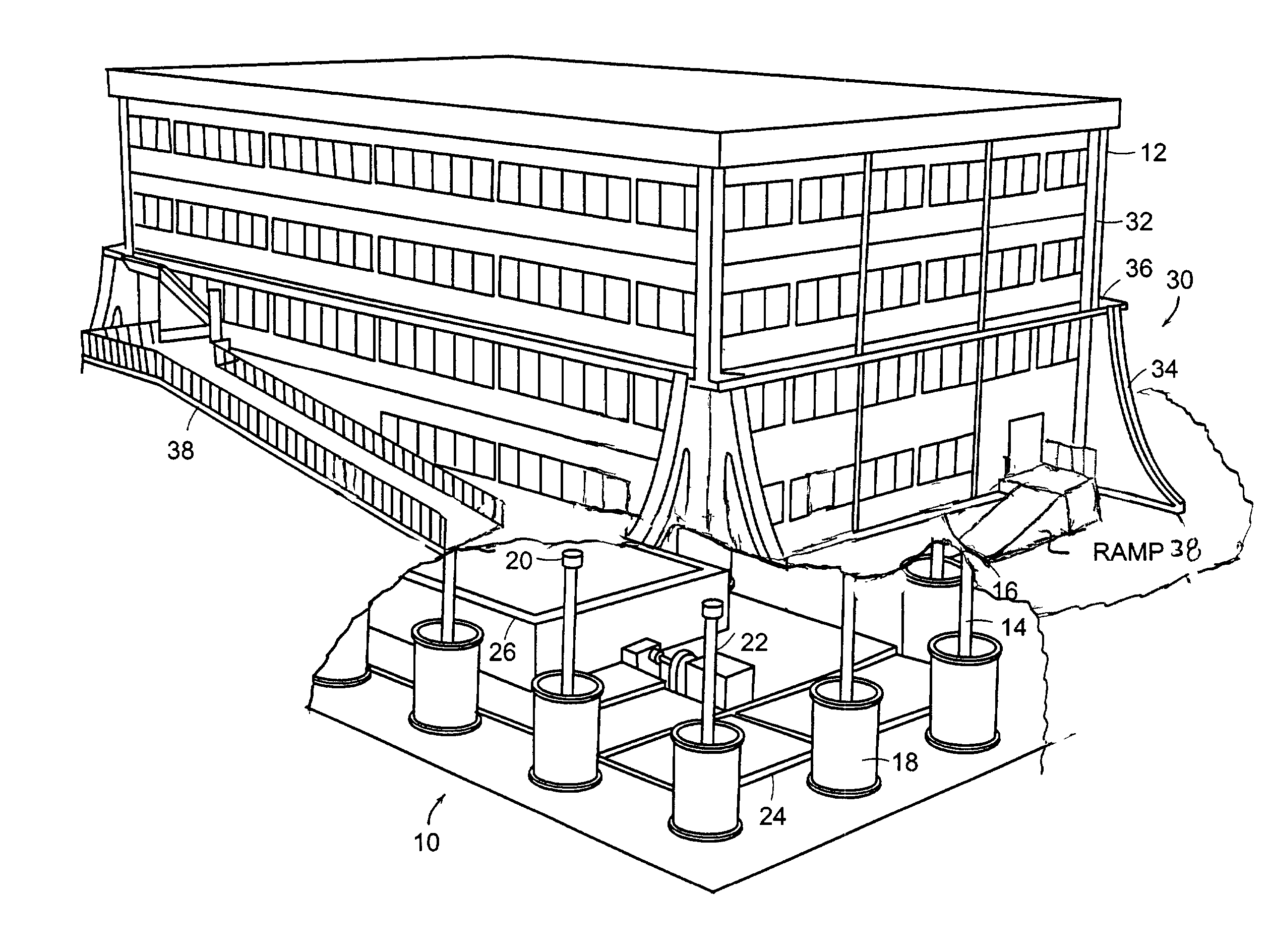
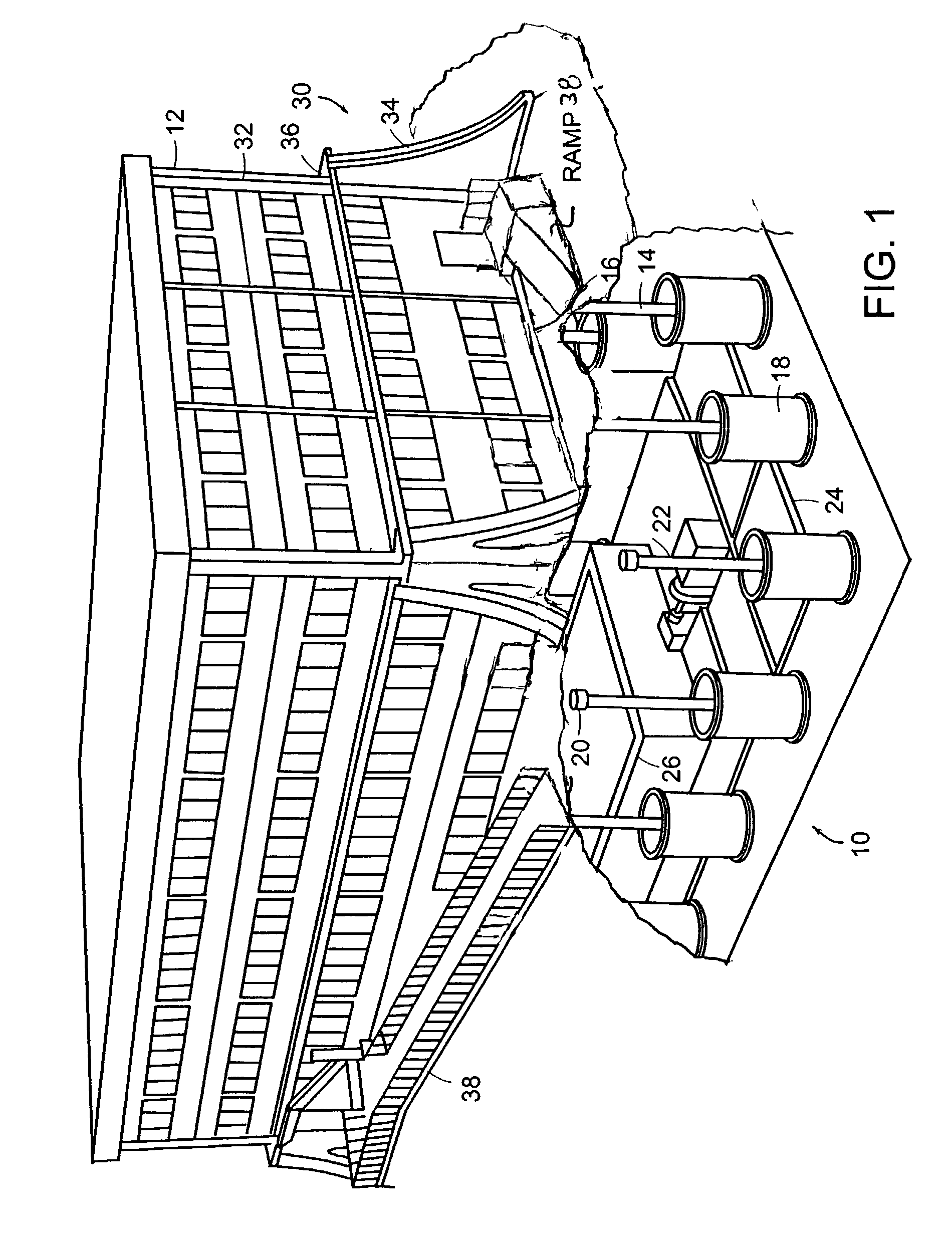
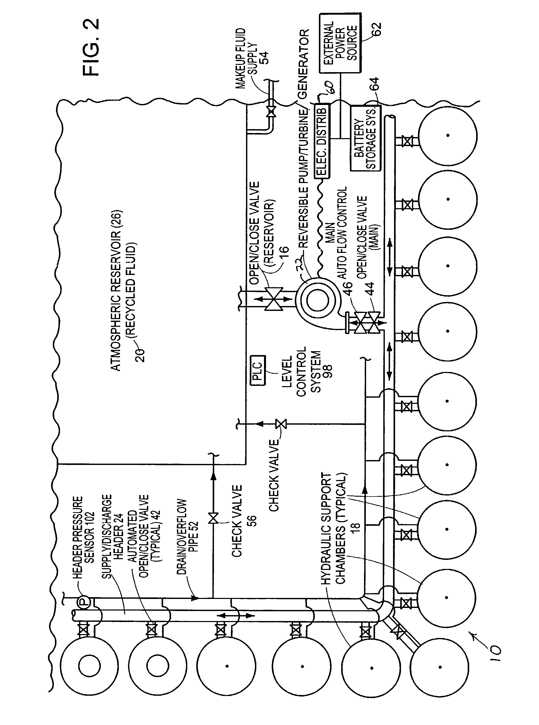
[0015]Various public utilities have used the “pumped storage” system which elevates large volumes of water several hundreds of feet to an upper reservoir, during off-peak hours when electrical power supplies are more available and less expensive. This stored energy, in the form of the potential energy of the elevated water, is then available on demand during peak periods. When required, the water is released, fed through large penstocks, into the inlet side of a large water-wheel-type turbine which is connected to a generator to produce electrical power. The prime-mover system used for this application is a reversible pump and turbine system which allows the generator to be run as a motor to drive the turbine in the reverse direction, thus operating as a pump to return the water again to the upper reservoir from the lower reservoir at the turbine discharge.

[0016]The current electric power market is focused on the need for addressing shortages of generation supply during peak-demand ...


PUM


Abstract

The present invention relates to a system for generating electrical power using hydraulic supports on which a building structure is mounted. A pump injects fluid into the supports to raise the building structure and thereby store energy in the elevated structure. A valve can be opened to deliver fluid under pressure to a turbine or hydraulic motor driven generator to generate electricity.

Description

CROSS REFERENCES TO RELATED APPLICATIONS[0001]The present application is a continuation-in-part of U.S. patent application Ser. No. 09 / 891,879, filed Jun. 26, 2001 now U.S. Pat. No. 6,860,068. The entire contents of the above application are incorporated herein by reference.BACKGROUND OF THE INVENTION[0002]Existing methods of electrical power generation used to provide alternative or backup power sources to established energy grid systems have various difficulties associated with them. These existing systems are often expensive, inefficient, have a limited lifetime and / or generation capacity.[0003]A continuing need exists for improvements in power generation, particularly to offset electrical power demands during peak loads.SUMMARY OF THE INVENTION[0004]The present invention relates to a power conversion system that supplies electrical power to buildings or other facilities. The system can be used to meet the load demand for a designated building during the daily peak load hours. In...

Claims


Application Information

Patent Timeline
Patent Type & Authority Patents(United States)
IPC IPC(8): B66B9/04E04B1/98E04H9/02F03B13/06F15B21/14
CPCF03B13/06F15B21/14Y02E60/17Y02E10/22Y02E10/20Y02E60/16
Inventor HALLORAN, JOHN J.
Owner HALLORAN JOHN J
Why Eureka
Try Eureka