
Generator control apparatus

a control apparatus and electric generator technology, applied in the direction of electric generator control, electric generator control, dynamo-electric converter control, etc., can solve the problems of ineffective generator operation, poor prevailing situation, insufficient control of electricity generation, etc., to improve the performance and efficiency of electric generators, and enhance reliability

Active Publication Date: 2006-02-07
MITSUBISHI ELECTRIC CORP
View PDF20 Cites 9 Cited by
  • Summary
  • Abstract
  • Description
  • Claims
  • Application Information

AI Technical Summary

Benefits of technology

[0012]In the light of the state of the art described above, it is an object of the present invention to provide an electric generator control apparatus which is capable of improving the performance and the efficiency of the electric generator with enhanced reliability by monitoring the temperature of the regulator itself and changing the contents of control in dependence on the temperature behavior.

Problems solved by technology

Accordingly, there may arise such undesirable situation that the operation temperature determined acceptable for the regulator exceeds the limit temperatures of the other constituents or parts.
In that case, if the temperature control is performed continuously only for the regulator, the prevailing situation will become worse.
Among others, control for the generation of electricity will become inadequate in the atmosphere of high temperature, incurring ineffectiveness in the generator operation.
In this conjunction, the temperature limit value of the IC regulator differs from the temperature limit values of the build-in or internal parts of the alternator, and it is impossible to realize matching of the temperature control between the regulator and the other parts.
Thus, there exists a problem that the temperature compensation or safeguard for the regulator and the other parts is insufficient.

Method used


Image

  • Generator control apparatus
  • Generator control apparatus
  • Generator control apparatus

Examples


embodiment 1

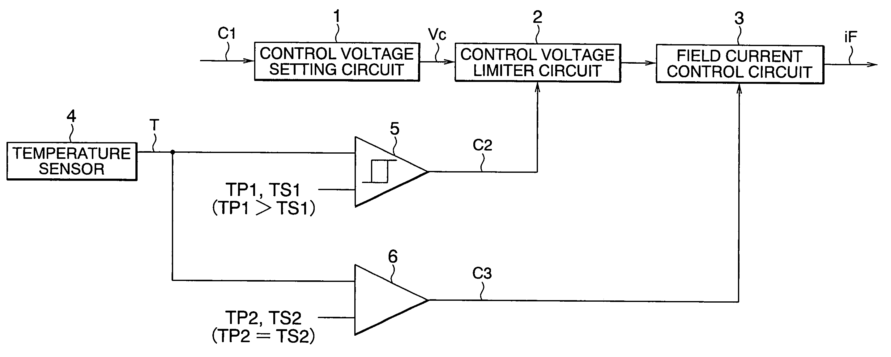
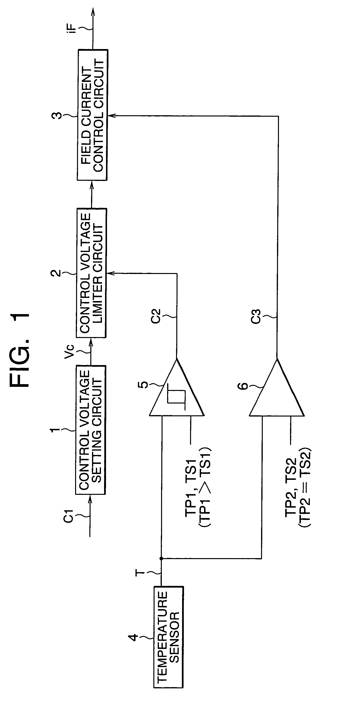
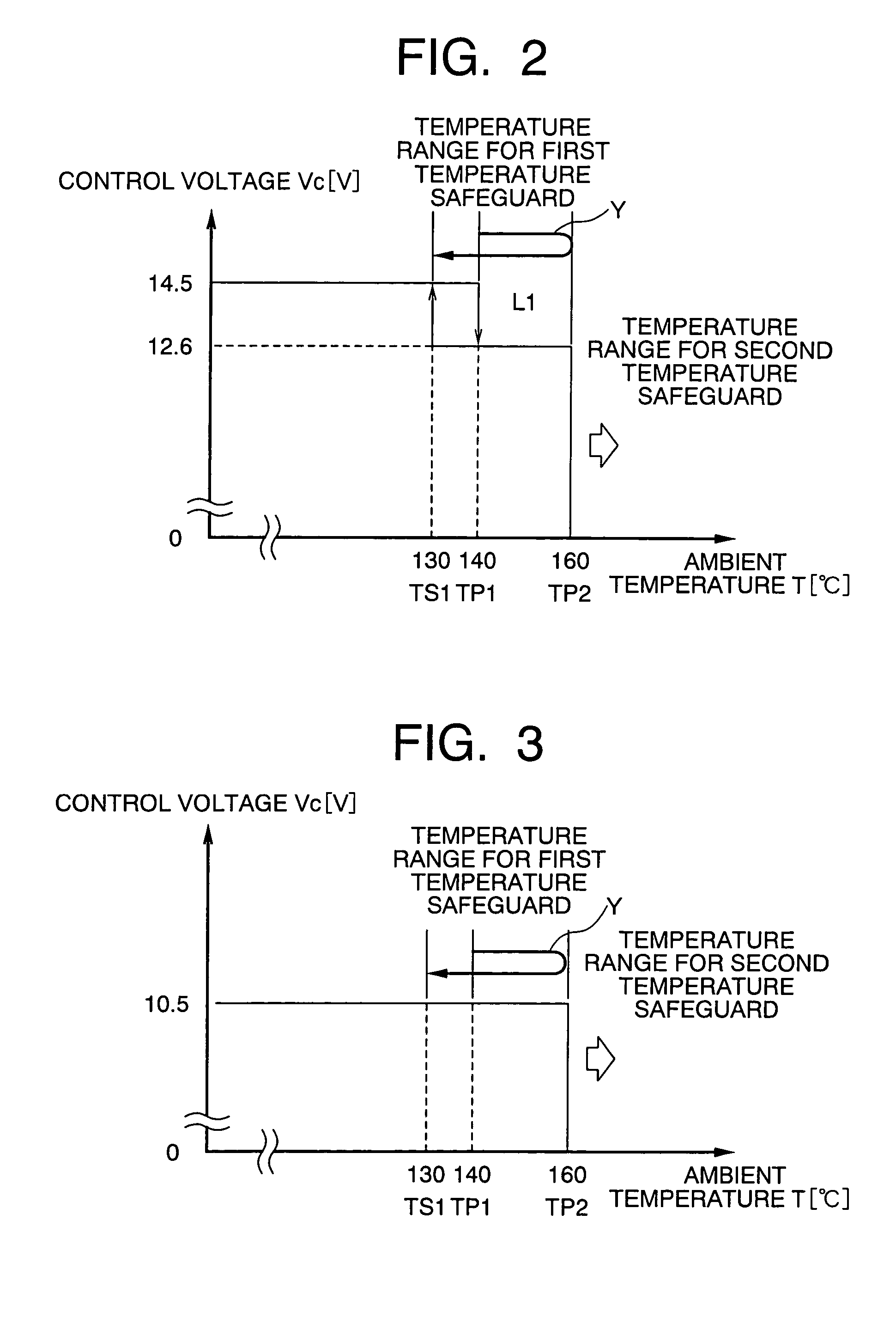
[0023]FIG. 1 is a functional block diagram for illustrating a functional arrangement of the IC regulator (i.e., electric generator control apparatus) according to a first embodiment of the present invention together with the circuit operation thereof. FIGS. 2 and 3 are views for graphically illustrating operation of the regulator according to the first embodiment of the invention, wherein FIG. 2 is a view for graphically illustrating operation of the regulator at various temperatures in the case where a control voltage described hereinafter is 14.5 volts while FIG. 3 is a view for graphically illustrating operation of the regulator at various temperatures in the case where the control voltage is 10.5 volts. Further, FIG. 4 is a block diagram showing an exemplary structure of an A / D (analog-to-digital) converter 40 employed in a temperature sensor 4 of the regulator shown in FIG. 1.

[0024]Referring to FIG. 1, the regulator (i.e., the generator control apparatus) denoted generally by a...


PUM


Abstract

An IC regulator for controlling an alternator by changing contents of control in dependence on ambient temperature includes a control voltage limiter (2), a field current controller (3), a temperature sensor (4), a first comparator (5) for comparing the ambient temperature (T) with an activation temperature (TP1) and a reset temperature (TS1), and a second comparator (6) for comparing the ambient temperature (T) with a second activation temperature (TP2). The first comparator (5) outputs a limiter control signal (C2) when the ambient temperature (T) exceeds the first activation temperature (TP1) while resetting the limiter control when the temperature (T) becomes lower than the first reset temperature (TS1). The second comparator (6) outputs a field current interrupt signal (C3) when the ambient temperature (T) exceeds a second activation temperature (TP2) while resetting the signal (C3) when the temperature (T) becomes lower than the second activation temperature (TP2).

Description

BACKGROUND OF THE INVENTION[0001]1. Field of the Invention[0002]The present invention generally relates to an electric generator control apparatus for controlling a field current of an electric generator on the basis of a control voltage conforming to a voltage indicating command. More particularly, the present invention is concerned with an electric generator control apparatus which is capable of enhancing the performance and the efficiency of an electric generator by monitoring the temperature of a regulator itself and changing contents of the control in dependence on the temperature behavior.[0003]2. Description of Related Art[0004]In general, the electric generator control apparatus (hereinafter also referred to as the regulator or IC regulator for the convenience of description) for regulating or controlling the field current and the generation voltage of the electric generator (hereinafter also referred to as the alternator for the convenience of description) is disposed inter...

Claims


Application Information

Patent Timeline
Patent Type & Authority Patents(United States)
IPC IPC(8): H02J7/14H02J7/00H02P9/04H02P9/14H02P9/00
CPCH02P9/006
Inventor SUMIMOTO, KATSUYUKISASAKI, JUNYAHIGASHINO, KYOKO
Owner MITSUBISHI ELECTRIC CORP
Learn More