Terminal-selective card connector

a card connector and selectivity technology, applied in the direction of coupling device connection, coupling/disconnecting parts, electrical apparatus, etc., can solve the problems of card being subject to interference with incompatible terminals, short circuit, card connector malfunction, etc., to avoid short circuit and selectivity

Inactive Publication Date: 2006-02-07
TAI SOL ELECTRONICS
View PDF5 Cites 12 Cited by
  • Summary
  • Abstract
  • Description
  • Claims
  • Application Information

AI Technical Summary

Benefits of technology

[0009]While a card compatible with the first group of terminals is inserted into the card connector, the second group of terminals can be suppressed to avoid contacting metallic parts of the card to further avoid short circuit. While a card compatible with the second group of terminals is inserted into the card connector, the card contacts the second group of terminals. Thus, the present invention enables selectivity of the terminals to cause different actions while different cards are inserted therein.

Problems solved by technology

However, all of the terminals of each of the aforesaid card connectors extend into the housing, while a card is inserted, the card is subject to interference with incompatible terminals.
Some erroneous insertion actions of a card, such as insertion of an upside-down card, may incur short circuit and malfunction of the card connector, or worse, damage of the circuits because metallic parts of one of some cards contact some terminals, or damage of the terminals because of abnormal contact of the terminals.

Method used


Image

  • Terminal-selective card connector
  • Terminal-selective card connector
  • Terminal-selective card connector

Examples


Embodiment Construction

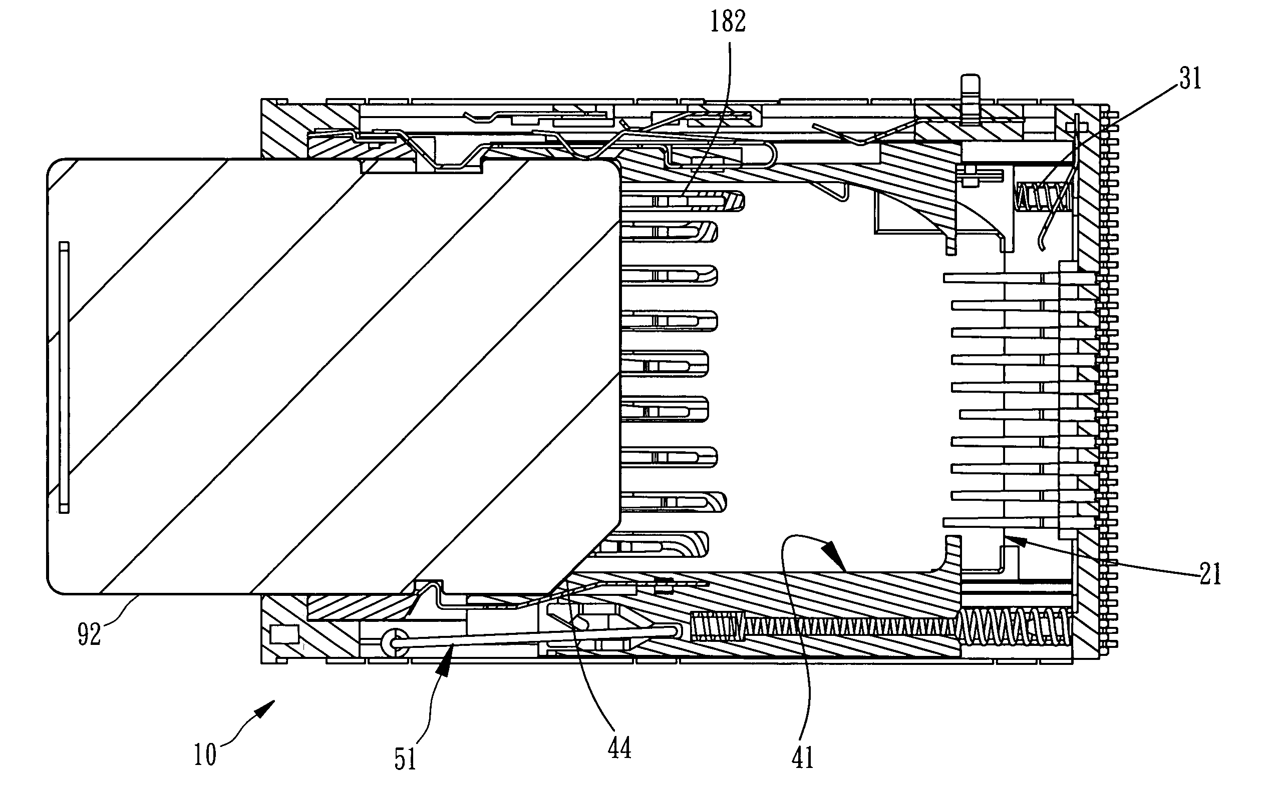
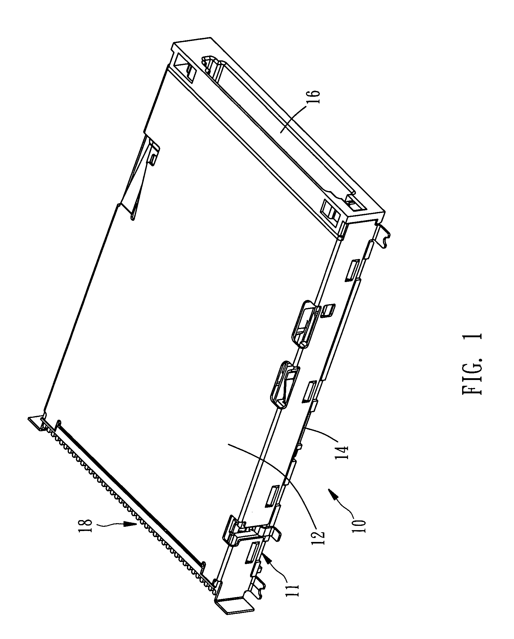
[0029]Referring to FIGS. 1–4, a card connector 10 constructed according to a preferred embodiment of the present invention is composed of a housing 11, a slide plate 21, a spring 31, a slide hood 41, and an injecting / ejecting device 51.

[0030]The housing 11 includes a cover shell 12 and a base frame 14 combined with the cover shell 12, having an opening 16 formed at a front end thereof. At least two groups of terminals 18 are mounted inside the housing 11 and extend into inside space of the housing 11, defining a first group of terminals 181 and a second group of terminals 182. The first group of terminals 181 is located at an internal rear end of the housing 11 for corresponding to an MS card, having a part elastically bending forward and upward. The second group of terminals 182 is located at an internal bottom side of the housing 11 for corresponding to an SD / MMC card, having a part elastically bending backward and upward.

[0031]The slide plate 21 is longitudinally slidably mounted...


PUM


Abstract

A terminal-selective card connector includes a housing, a slide plate, a spring, a slide hood, and an injecting/ejecting device. At least two groups of terminals are mounted inside the housing. The slide plate is longitudinally slidably mounted at an internal lower side of the housing, having a plurality of elongated slots and a first action point located at a rear end thereof. The second group of terminals runs through bottom sides and then top sides of the elongated slots. The spring is mounted inside the housing for keeping forward movement of the slide plate. The slide hood has a second action point and a stopping portion for contacting against an inserted predetermined card. The injecting/ejecting device is mounted inside the housing for working on the slide hood. Thus, selectivity of the terminals is effected to enable different actions while different cards are inserted.

Description

BACKGROUND OF THE INVENTION[0001]1. Field of the Invention[0002]The present invention relates generally to electronic apparatuses, and more particularly, to a terminal-selective card connector.[0003]2. Description of the Related Art[0004]Referring to FIG. 18, a conventional all-in-one card connector 70 for compatibly accommodating multiple kinds of electronic cards includes a housing 71, several receiving rooms formed inside the housing 71 and partially overlapping for receiving the cards, and many groups of terminals mounted inside the housing 71 for electrical connection respectively with corresponding contact pins of different cards, for the purpose of transitional connection. Referring to FIG. 19, another conventional card connector 80 includes an injecting / ejecting device mounted inside a housing 81 thereof for securing an inserted card at a lockup position for access and then ejecting the card while the card is pushed further again.[0005]However, all of the terminals of each o...

Claims


Application Information

Patent Timeline
Patent Type & Authority Patents(United States)
IPC IPC(8): H01R13/62H01R13/703H01R27/00
CPCH01R13/7039H01R27/00
Inventor LAI, YAW-HUEY
Owner TAI SOL ELECTRONICS
Why Eureka
Try Eureka