Failure detection apparatus for an internal combustion engine

a failure detection and internal combustion engine technology, applied in mechanical devices, machines/engines, electric control, etc., can solve the problems of inability to determine the failure of the air flow sensor with accuracy, the failure of the exhaust gas characteristics may possibly be deteriorated, and the inability to suspend the diagnosis, etc., to achieve reliable detection of abnormalities

Inactive Publication Date: 2006-02-07
MITSUBISHI FUSO TRUCK AND BUS CORPORATION
View PDF12 Cites 11 Cited by
  • Summary
  • Abstract
  • Description
  • Claims
  • Application Information

AI Technical Summary

Benefits of technology

[0012]The present invention was created to solve the above problems, and an object thereof is to provide a failure detection apparatus for an internal combustion engine which is capable of reliable detection of abnormality in an air flow sensor irrespective of vane opening control of a variable nozzles / vanes-equipped supercharger.

Problems solved by technology

If any of the sensors etc. fails, however, the exhaust gas characteristics may possibly be deteriorated, and accordingly, there has been a demand for reliable detection of failure of such sensors etc.
However, in the case where the exhaust flow rate (exhaust pressure) is adjusted by means of the variable nozzles / vanes of a variable nozzles / vanes-equipped supercharger (VG turbocharger) or where EGR gas is introduced into the intake system while the exhaust flow rate is adjusted by the variable nozzles / vanes, the quantity of fresh air varies depending on the vane opening of the variable nozzles / vanes or the opening of the EGR valve, giving rise to a problem that failure of the air flow sensor cannot be determined with accuracy.
Such suspension of the diagnosis is, however, not desirable because it leads to a substantial reduction in the period for diagnosing the air flow sensor.

Method used


Image

  • Failure detection apparatus for an internal combustion engine
  • Failure detection apparatus for an internal combustion engine
  • Failure detection apparatus for an internal combustion engine

Examples


first embodiment

[0060]A first embodiment will be explained first.

[0061]FIG. 3 is a flowchart illustrating a control routine for air flow sensor (AFS) failure determination, executed in the failure detection apparatus according to the first embodiment of the present invention. The control routine will be described with reference to the flowchart.

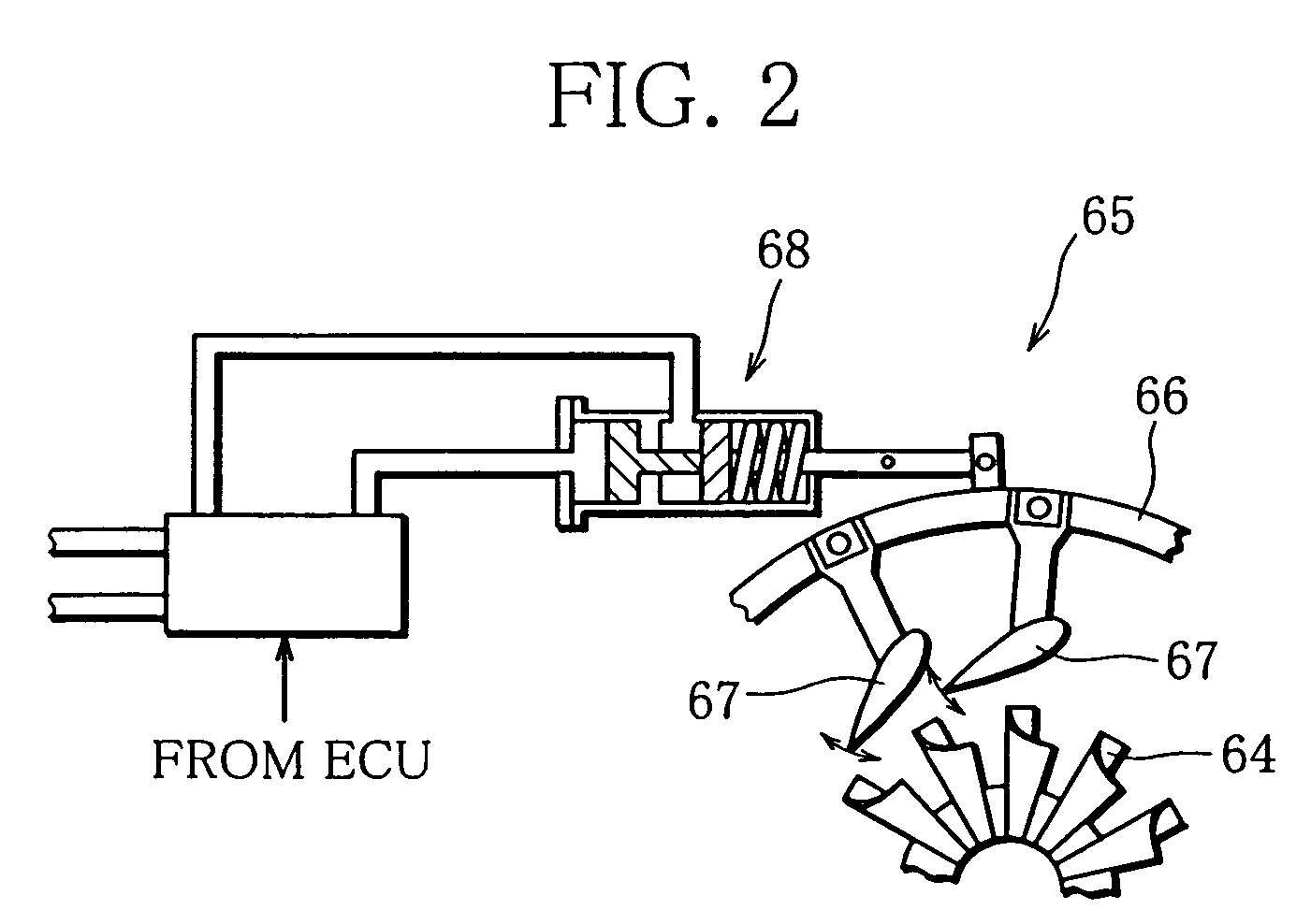
[0062]First, in Step S10, it is determined whether or not vane opening control is under execution, that is, whether or not the exhaust flow rate (exhaust pressure) is being adjusted by controlling the opening of the variable nozzles / vanes 67. Specifically, it is determined whether or not the vane opening control is performed to secure sufficient boost pressure in such a situation where the engine speed Ne or engine load is low and thus the exhaust flow rate is low. If the decision in this step is affirmative (Yes) and thus the vane opening control is under execution, the routine proceeds to Step S12.

[0063]In Step S12, a target vane opening for the variable n...

second embodiment

[0076]A second embodiment will be now described.

[0077]FIG. 4 is a flowchart illustrating a control routine for air flow sensor (AFS) failure determination, executed in the failure detection apparatus according to the second embodiment of the present invention. In the following description of the flowchart, only the differences between the first and second embodiments will be explained.

[0078]In the second embodiment, after the target vane opening is set in Step S12, the fresh air quantity reference value is set immediately thereafter based on the target vane opening in Step S16, without correcting the target vane opening, unlike the first embodiment.

[0079]Then, in Step S17, it is determined whether or not the actual excess air ratio λ detected by the λ sensor 26 is equal to the target value λ1 (λ=λ1). In other words, it is determined whether or not a difference between the target value λ1 and the actual excess air ratio λ has been caused due to an opening difference between the actua...

third embodiment

[0085]A third embodiment will be now described.

[0086]FIG. 5 is a flowchart illustrating a control routine for air flow sensor (AFS) failure determination, executed in the failure detection apparatus according to the third embodiment. In the following description of the flowchart, only the differences between the third embodiment and the first or second embodiment will be explained.

[0087]In the third embodiment, after the target vane opening is set in Step S12, the fresh air quantity reference value is set immediately thereafter based on the target vane opening in Step S16, like the second embodiment.

[0088]Then, in Step S17, it is determined whether or not the actual excess air ratio λ detected by the λ sensor 26 is equal to the target value λ1 (λ=λ1), as in the second embodiment.

[0089]If the decision in Step S17 is affirmative (Yes) and it is judged that the actual excess air ratio λ and the target value λ1 are equal, it can be concluded that the target vane opening has been set to ...


PUM


Abstract

A failure detection apparatus for an internal combustion engine includes failure detecting means (S22–S30) for detecting abnormality of fresh air quantity detecting means (air flow sensor) based on the result of comparison between a fresh air quantity detected by the fresh air quantity detecting means (air flow sensor) and a fresh air quantity reference value set by fresh air quantity reference value setting means (S20), and a supercharger equipped with variable nozzles/vanes. The fresh air quantity reference value setting means sets the reference value (S16) in accordance with not only the operating state (engine speed Ne, fuel injection quantity Qf, etc.) of the engine but also a target vane opening set for the variable nozzles/vanes of the supercharger by target vane opening setting means (S12, S14).

Description

BACKGROUND OF THE INVENTION[0001]1. Field of the Invention[0002]The present invention relates to a failure detection apparatus for an internal combustion engine, and more particularly, to techniques enabling reliable detection of abnormality in an air flow sensor.[0003]2. Description of the Related Art[0004]Recently, in order to prevent harmful exhaust gas from being emitted from an engine mounted on a motor vehicle, various control means are used to improve exhaust gas characteristics. These control means operate based on information supplied from various sensors and the like, to improve the exhaust gas characteristics.[0005]If any of the sensors etc. fails, however, the exhaust gas characteristics may possibly be deteriorated, and accordingly, there has been a demand for reliable detection of failure of such sensors etc. Recently, vehicles equipped with an on-board diagnostic system (OBD etc.) have been developed and put to practical use, with a view to further improving the exhau...

Claims


Application Information

Patent Timeline
Patent Type & Authority Patents(United States)
IPC IPC(8): F02D23/00F02B33/44F02D45/00F02M25/07F02B37/00F02B37/24F02B39/16F02D41/00F02D41/18F02D41/22F02D43/00
CPCF02D41/18F02M25/0702F02D41/222F02B37/24F02D41/0007Y02T10/40F02M25/0707F02M26/05F02M26/49F02D41/22
Inventor AKAO, YOSHIYUKIKOHKETSU, SUSUMU
Owner MITSUBISHI FUSO TRUCK AND BUS CORPORATION
Why Eureka
Try Eureka