
Card connector having an eject mechanism adaptable to a plurality of kinds of cards different in size

a card connector and eject mechanism technology, applied in the direction of coupling device connection, conveying record carriers, instruments, etc., can solve the problems of disadvantage of above-mentioned card connectors and difficulty in reducing the size of card connectors

Inactive Publication Date: 2006-01-31
JAPAN AVIATION ELECTRONICS IND LTD
View PDF8 Cites 43 Cited by
  • Summary
  • Abstract
  • Description
  • Claims
  • Application Information

AI Technical Summary

Benefits of technology

The invention is a card connector that can use different types of cards without ejecting them in the wrong direction. It has multiple ejecting members that move independently and can be selectively linked to each other when a card is inserted. This allows for reliable ejection of multiple cards simultaneously. The connector is designed to be durable and easy to use with different types of cards.

Problems solved by technology

If a plurality of eject mechanisms are provided in correspondence to a plurality of kinds of cards, the card connector has a complicated structure which makes it difficult to reduce the size of the card connector.
However, the above-mentioned card connector is disadvantageous in the following respects.
However, the connector is not designed so as to use a single large card having a width corresponding to that of the two cards arranged in the widthwise direction.

Method used


Image

  • Card connector having an eject mechanism adaptable to a plurality of kinds of cards different in size
  • Card connector having an eject mechanism adaptable to a plurality of kinds of cards different in size
  • Card connector having an eject mechanism adaptable to a plurality of kinds of cards different in size

Examples


Embodiment Construction

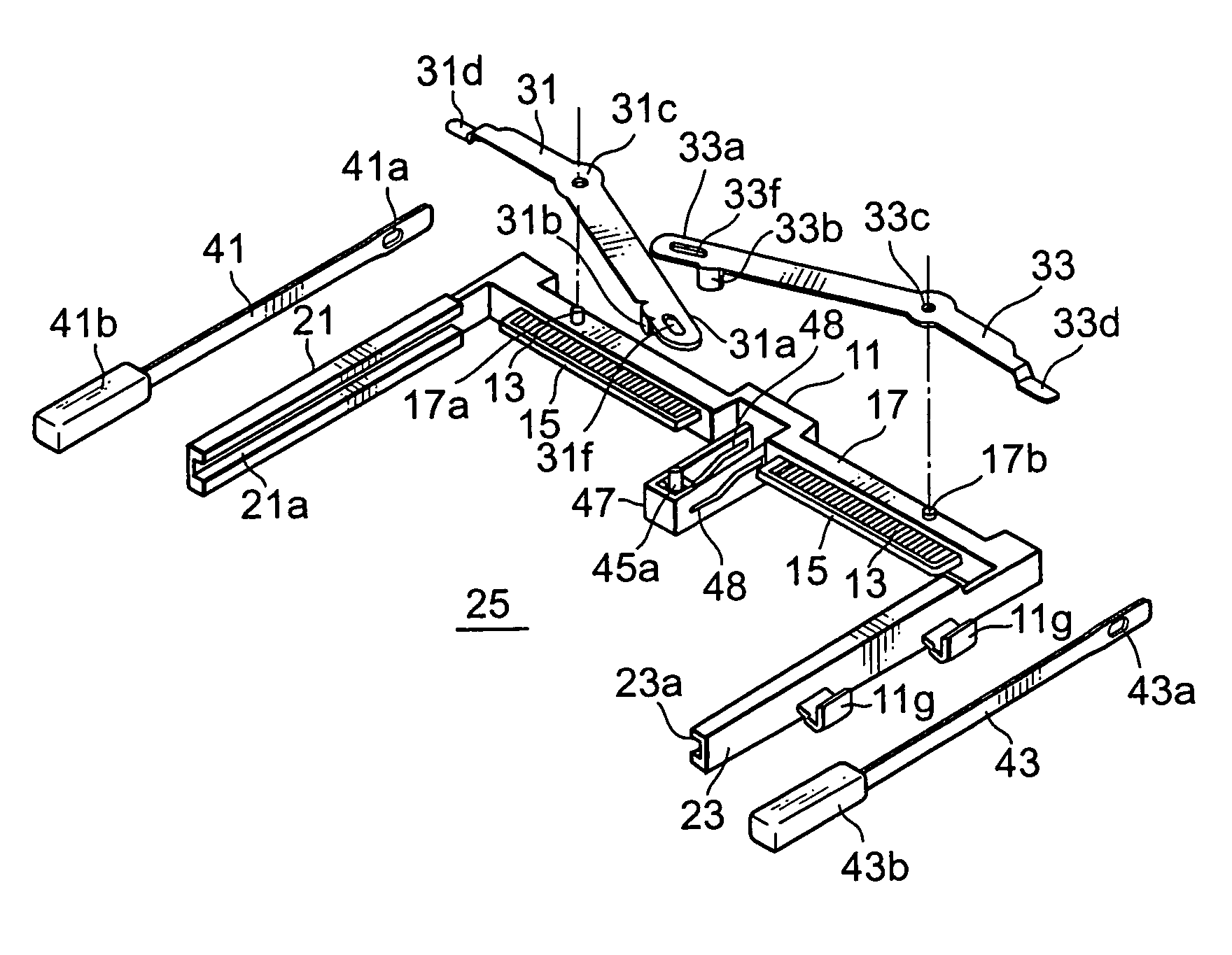
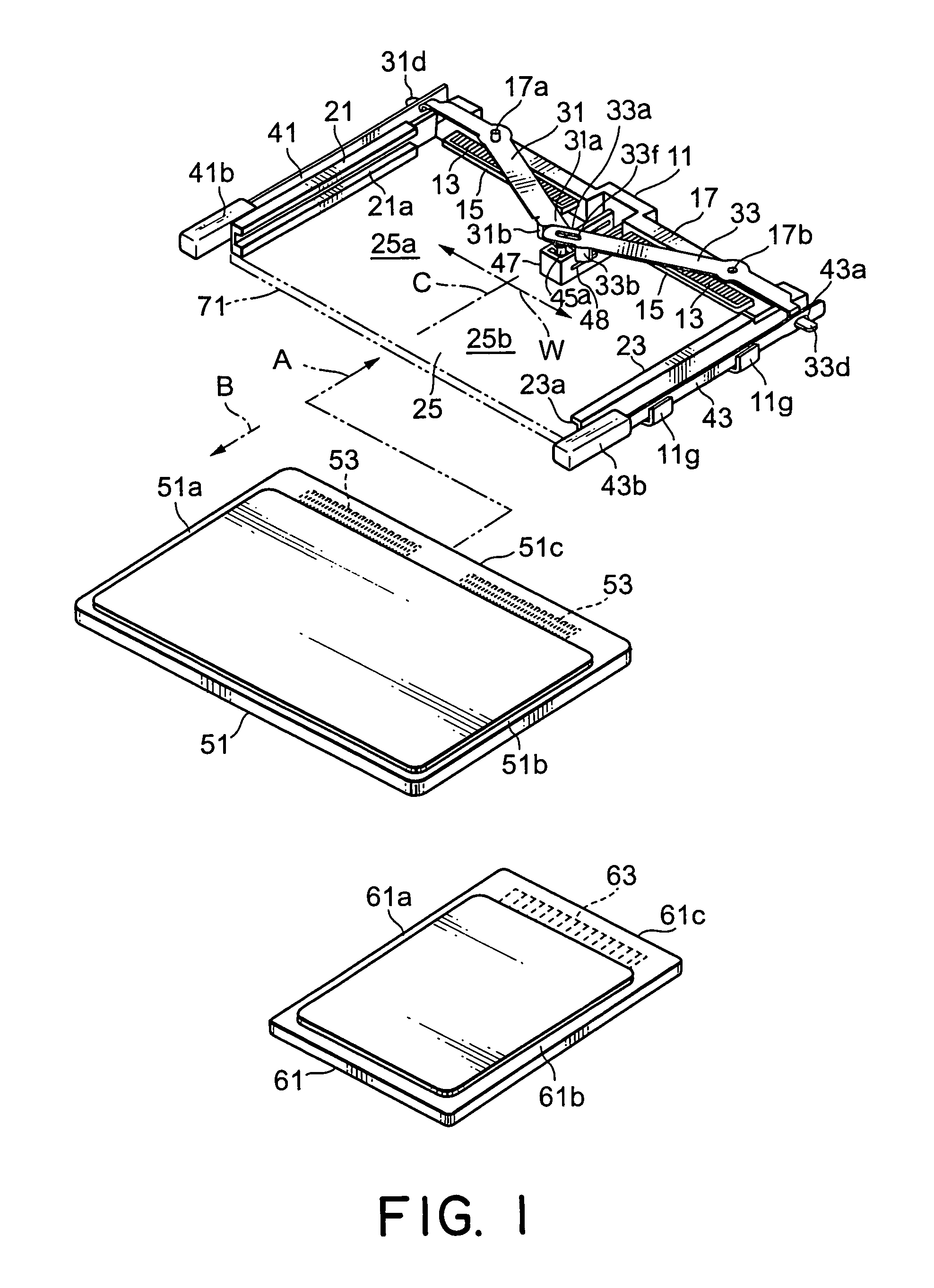
[0021]Referring to FIGS. 1 and 2, description will be made of a card connector according to an embodiment of this invention.

[0022]The card connector illustrated in the figure serves to connect an IC card used in an electronic apparatus. By the use of the card connector, it is possible to selectively connect a wide IC card (hereinafter called a first card 51) and a narrow IC card (hereinafter called a second card 61). Thus, the card connector is capable of connecting only one card which may be the first card 51 or the second card 61 and of simultaneously connecting two second cards 61. In the present specification, the first card 51 and the second card 61 may collectively and simply be called a card.

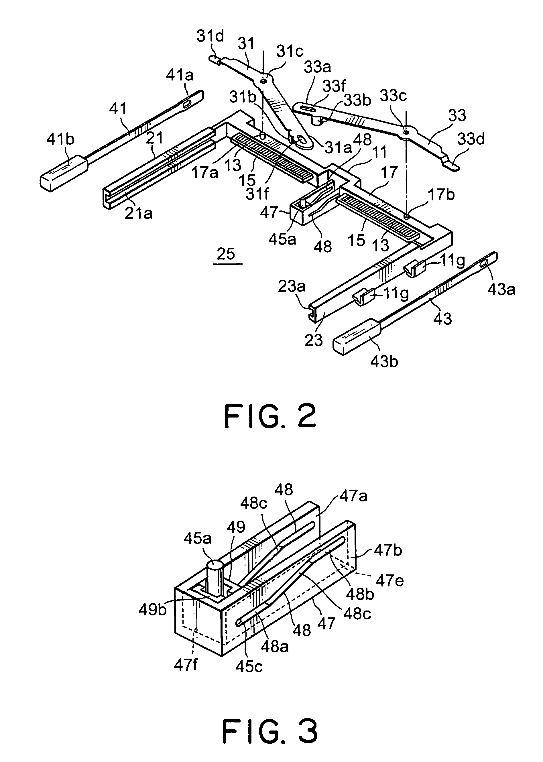
[0023]The card connector comprises a defining member, i.e., a generally U-shaped insulator 11 defining an insertion region for inserting the card, a plurality of conductive contacts 13 fixed to the insulator 11, and an eject mechanism for ejecting the card from the insertion region. The c...


PUM


Abstract

In a card connector to be connected to a card, a defining member defines an inserting region for receiving the card inserted in an inserting direction. The card connector includes an eject mechanism for ejecting the card from the inserting region in an ejecting direction opposite to the inserting direction. A plurality of ejecting members are adapted to be engaged with the card in the inserting region in the inserting and the ejecting directions and movable with respect to the defining member independently of one another. A linking mechanism selectively links the ejecting members to each other in response to insertion of the card in the inserting region.

Description

[0001]This application claims priority to prior Japanese patent application JP 2003-421816, the disclosure of which is incorporated herein by reference.BACKGROUND OF THE INVENTION[0002]This invention relates to a card connector having an eject mechanism for ejecting a card.[0003]Recently, a plurality of kinds of cards different in size are used in various fields. Under the circumstances, there arises a demand for a card connector allowing those cards to be used in the same card connector. In this case, an eject mechanism for ejecting a card must be adaptable to such a plurality of kinds of cards. If a plurality of eject mechanisms are provided in correspondence to a plurality of kinds of cards, the card connector has a complicated structure which makes it difficult to reduce the size of the card connector. Further, in case where a card has a large width, it is desired that the eject mechanism uniformly applies an ejecting force to the card.[0004]For example, Japanese Patent Applicat...

Claims


Application Information

Patent Timeline
Patent Type & Authority Patents(United States)
IPC IPC(8): H01R13/62H01R13/633G06K13/08H01R13/44H01R13/629
CPCG06K7/0043G06K13/0806G06K13/08
Inventor KATAYANAGI, MASAYUKIKAMATA, KAZUSHI
Owner JAPAN AVIATION ELECTRONICS IND LTD
Learn More