Eureka AIR delivers breakthrough ideas for toughest innovation challenges, trusted by R&D personnel around the world.

Ink control mechanism for a pen

a control mechanism and pen technology, applied in the field of pen, can solve the problems of short lifespan and volume of leakage of ink, quick consumption, short lifespan of ink leakage, etc., and achieve the effect of convenient mass production and simple production

Inactive Publication Date: 2006-01-31
HUANG TAO TIEN
View PDF4 Cites 5 Cited by
  • Summary
  • Abstract
  • Description
  • Claims
  • Application Information

AI Technical Summary

Benefits of technology

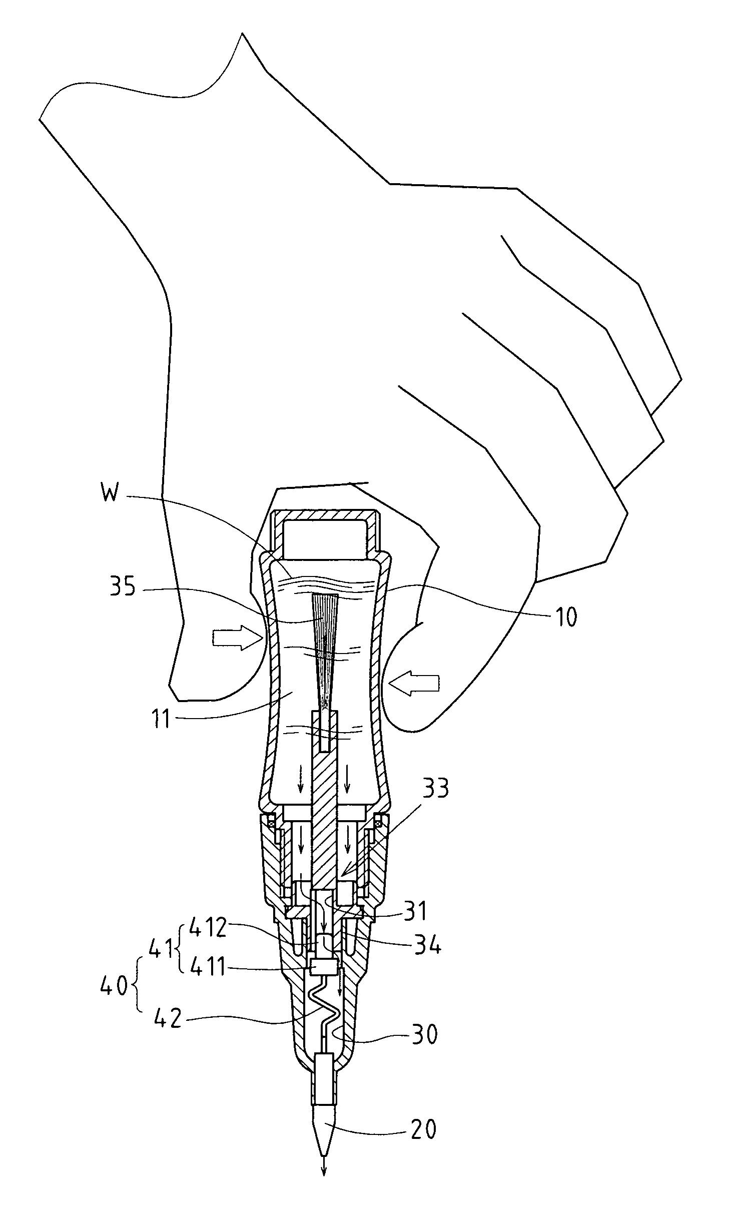
[0012]2. According to this specially improved structure, in usage of the pen, the object of ink supply can be reached by means of pinching the pen body; while in spare, the ink supply of the pen point will automatically be failed by the control valve to achieve the practical effect of preventing continuous ink volatilization, prolonging ink lifespan and avoiding volumes of ink leakage, which enable it to meet the requirements of novelty of a new-pattern patent.
[0014]1. Wherein the stopper end 41 and elastic part 42 can be of plastic-rubber extrusion molding type, thus being simple to make and easy for mass production.
[0015]2. The end of the pen where pen point 20 is arranged can be covered with a pen cap 50. When the pen cap 50 is in covering state, the user will fail to pinch the pen body 10 due to the failure of pressure release in the empty cavity 11, thus to prevent the ink from flowing out due to unintentional pressing of the pen body when the pen is not used.

Problems solved by technology

However, it is found from the conventional structure that, the interior ink, especially the volatile ink, can be exhausted continuously from a pen point, resulting in such defects as quick consumption, short lifespan and volumes of leakage of ink.
However, in practical application, it is found from the known structure that, due to a cotton strip's smaller ink absorption and content than that of aforesaid structure, and continuous exhaustion from the pen point, it possesses such disadvantages as quick consumption, short lifespan and the need of frequent supply or even rejection.

Method used


Image

  • Ink control mechanism for a pen
  • Ink control mechanism for a pen
  • Ink control mechanism for a pen

Examples


Embodiment Construction

[0026]The features and the advantages of the present invention will be more readily understood upon a thoughtful deliberation of the following detailed description of a preferred embodiment of the present invention with reference to the accompanying drawings.

[0027]As shown in FIGS. 1–4, there is a nail painting pen embodied in the present invention that provides enhanced ink control mechanism.

[0028]The present invention includes an empty pen body 10 with an empty cavity 11 internally to contain the supplied liquid ink (e.g. nail oil in the embodiment), and the surrounding wall of the pen body 10 is flexible and can be pinched and bring pressure to the empty cavity11.

[0029]The invention also includes a pen point 20 configured at the end of pen body 10. The material and type of the pen point are of no limitation and can include currently popular fiber material or ballpoint pen point. The pen point 20 shall have hydraulic conductivity to lead the ink out.

[0030]There is an ink supply pa...


PUM


Abstract

The ink control structure of a pen includes a pen body and a pen point. The interior of the pen body is an empty cavity for containing ink and the surrounding wall of the pen body is flexible and can be pinched. The inner end of the pen point joins the empty cavity via an ink supply passage. The pen point has hydraulic conductivity and can lead the ink out. The pressure-driven control valve is configured into the ink supply passage and includes a stopper end and an elastic part. The elastic part can normally push the stopper end to pressingly meet a narrow opening in the ink supply passage, thus forming a state that the ink is prevented from a flow out. While under pressure, the ink supply passage is opened to make ink flow downward to the pen point for applying or writing.

Description

RELATED U.S. APPLICATIONS[0001]Not applicable.STATEMENT REGARDING FEDERALLY SPONSORED RESEARCH OR DEVELOPMENT[0002]Not applicable.REFERENCE TO MICROFICHE APPENDIX[0003]Not applicable.FIELD OF THE INVENTION[0004]The present invention relates generally to a pen, and more particularly to a structurally and spatially innovative pen that has a pressure-driven control valve at the inner end of its pen point, which will block the ink supply passage under the push of the elastic part thereof, and the ink passage will then be opened when the pen body is pressed so as to let ink flow to the pen point.BACKGROUND OF THE INVENTION[0005]Generally, pens have different functions and types according to the difference of its interior ink such as nail painting pens, light extinction pens, marker pens and color pens etc., whose structures are equally characterized by pen points and empty pen bodies and the main difference comes from the ink set therein. About the ink currently available, their structur...

Claims


Application Information

Patent Timeline
IPC IPC(8): B43M11/06A47L1/08B05C1/00B43K5/00
CPCB43K5/04B43K27/08B43K7/10B43K8/04B43K5/1836A45D34/045
Inventor HUANG, TAO-TIEN
Owner HUANG TAO TIEN
Why Eureka
Eureka Blog
Learn More