
Log splitting head for bundlewood production

a splitting head and bundlewood technology, applied in the direction of lifting devices, building parts, construction, etc., can solve the problems of high cost of equipment, large size and limited portability, and difficulty in stacking wood in a fireplace,

Inactive Publication Date: 2006-01-31
SMITH JOHN R
View PDF5 Cites 10 Cited by
  • Summary
  • Abstract
  • Description
  • Claims
  • Application Information

AI Technical Summary

Benefits of technology

"The present invention is a multi-wedge splitting head for a log splitting apparatus that can effectively split wood into smaller pieces. The splitting head has a primary assembly with two wedge members and a secondary assembly with two sets of wedge members. The secondary assembly is positioned behind the primary assembly and produces a square aperture. Banding means can be added to consolidate the wood pieces. The technical effect of this invention is to provide a more efficient and effective way to split wood into smaller pieces."

Problems solved by technology

Certain difficulties are encountered in seeking such result.
If all the splitting is sought to be accomplished in a single pass through one splitting head, the requisite ram pressure would be extremely high, thereby necessitating equipment of high cost, large size and limited portability.
Such sector shape, in small dimensions, causes difficulties in stacking wood in a fireplace.
Also, the very thin tips are very splintery, producing frequent jamming in the splitting heads, and further cause some handling discomfort to the user.

Method used


Image

  • Log splitting head for bundlewood production
  • Log splitting head for bundlewood production
  • Log splitting head for bundlewood production

Examples


Embodiment Construction

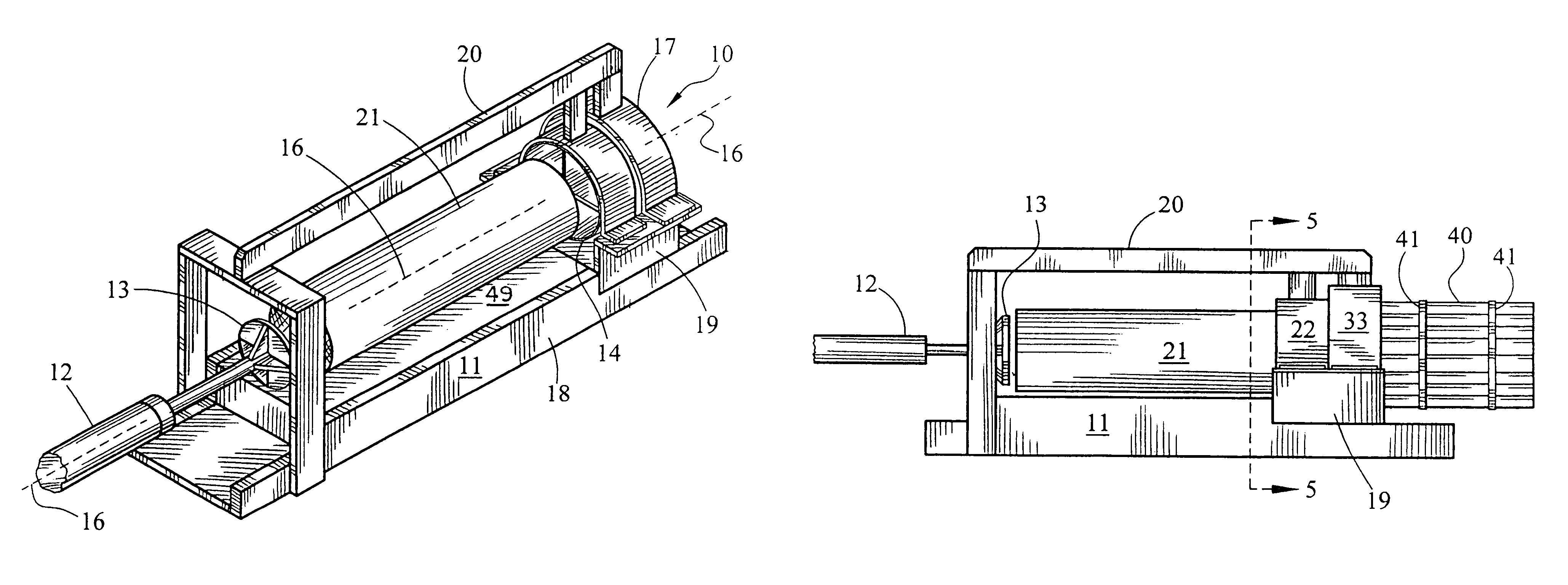
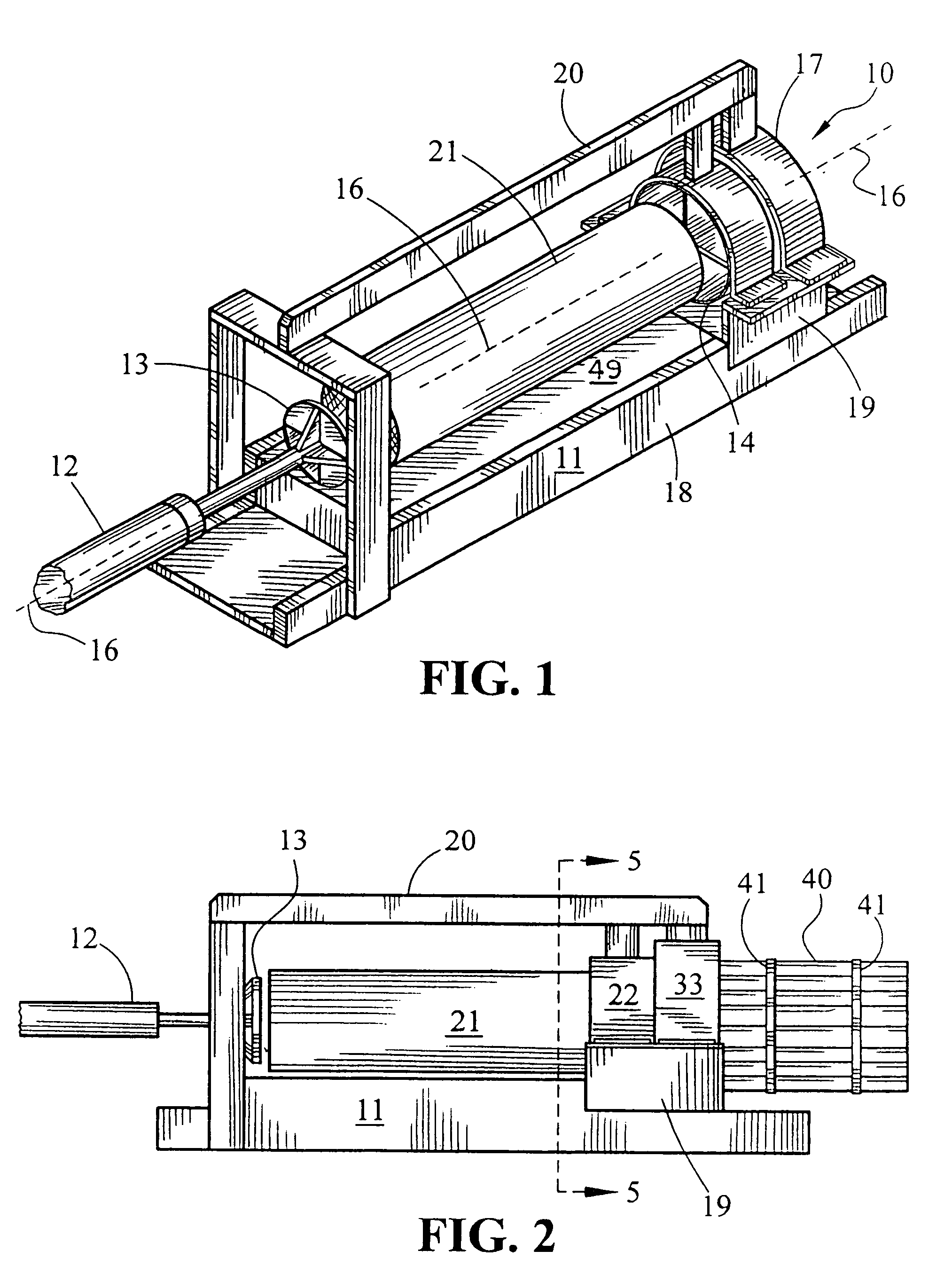
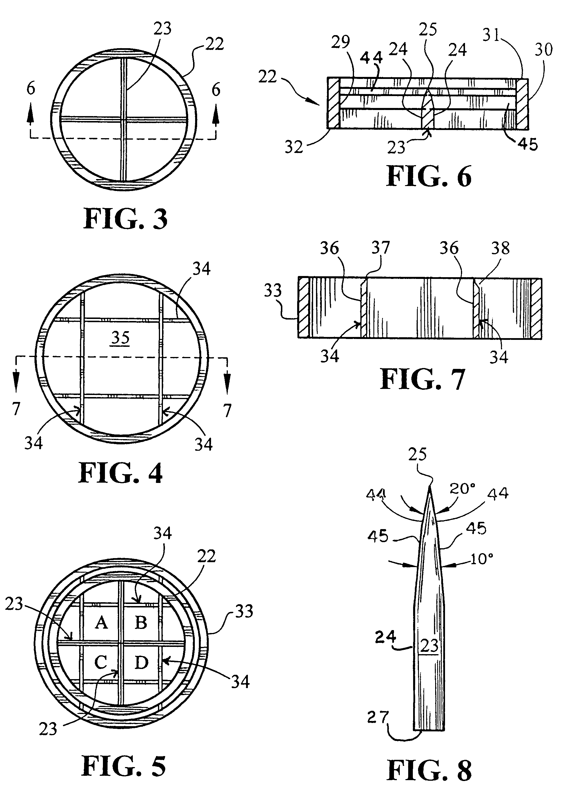
[0027]Referring now to FIGS. 1–7, an embodiment of the log splitting head 10 of the present invention is shown installed into a splitting apparatus having an elongated structural base 11, and a hydraulic ram 12 acting in the longitudinal direction of the base upon axis 16 and terminating in a pusher plate 13 which may be rotatable about the axis of the ram. Said ram is capable of exerting a force of between about 20 and 30 tons upon said logs.

[0028]Splitting head 10 is comprised of a primary splitting assembly 14 mounted in facing relationship with said pusher plate and in axial alignment therewith, and secondary splitting assembly 17 mounted rearwardly of assembly 14 and in contact therewith. Said assemblies are secured to base 11 by bottom, side and top structural members 18, 19 and 20, respectively. A log 21 readied for splitting is placed upon base 11 and advanced by ram 12 toward splitting head 10. Guiding track means 49 may be associated with base 11 to facilitate proper movem...


PUM


Abstract

A splitting head for a log splitting apparatus includes abutting primary and secondary splitting assemblies, each having a circular securing ring that holds wedge members having cutting edges directed toward the log. The cutting edges of the secondary assembly split into smaller pieces the pieces produced by the primary assembly, producing a bundle of elongated pieces of firewood in parallel array and wherein the center of the bundle has not been compressed.

Description

BACKGROUND OF THE INVENTION[0001]1. Field of the Invention[0002]This invention relates to apparatus for the splitting of wooden logs into small pieces useful as firewood.[0003]2. Description of the Prior Art[0004]Devices for converting logs into firewood generally employ a hydraulically driven ram-type mechanism which forces logs of pre-cut length into a stationary wedge having sharpened edges. As the log is axially advanced into the wedge, it splits into a plurality of sector-shaped pieces along cleavage lines that are generally directed radially with respect to the center axis and along medullar rays of the log. Typical examples of such devices are disclosed in U.S. Pat. Nos. 4,294,295; 4,353,401; 4,371,019; and 5,287,902.[0005]In the production of firewood, there is considerable demand for “kindling” wood, namely pieces of firewood of small cross section which are easily ignited. The kindling wood, generally having a cross-sectional dimension less than about 3 inches, is further ...

Claims


Application Information

Patent Timeline
Patent Type & Authority Patents(United States)
IPC IPC(8): B27L7/00
CPCB27L7/06
Inventor SMITH, JOHN R.
Owner SMITH JOHN R
Learn More