
Piezoelectric transformer

a technology of electric transformer and electric motor, which is applied in the direction of generator/motor, machine/engine, instruments, etc., can solve the problems of disadvantageous increase of winding loss, small size and thinness of electromagnetic transformer, and the inability to commercialize the product. achieve the effect of high circuit efficiency

Inactive Publication Date: 2006-01-24
PANASONIC CORP
View PDF17 Cites 4 Cited by
  • Summary
  • Abstract
  • Description
  • Claims
  • Application Information

AI Technical Summary

Benefits of technology

[0033]It is a first object of the present invention to provide a reliable piezoelectric transformer capable of handling high power.

Problems solved by technology

A piezoelectric transformer which was designed for a step-up transformer of a high voltage power supply has not been commercialized because of limited properties of a piezoelectric ceramic material such as breaking strength.
However, there is a limit to making the electromagnetic transformer small in size and thin because it needs to have a withstand voltage against the voltage as high as several kVrms.
Further, winding loss disadvantageously increases and transform efficiency disadvantageously decreases because a thin copper wire is employed to increase the number of turns for stepping up voltage.
Besides, the loss disadvantageously occurs which is caused by the material of the core.
Generally, when extremely large strains are caused by the mechanical vibrations in a piezoelectric transformer, the possibility that a piezoelectric transformer will break is high, which leads to a deterioration in reliability.
However, if a space in which the piezoelectric transformer can be arranged is restricted in a system or an equipment into which the piezoelectric transformer is introduced, there is a limit to holding down elastic strains only by its shape.
As a result, also in this case, as in the case where the piezoelectric transformer handles high power, the piezoelectric transformer which is high in reliability as well as small in size and thin cannot be realized in terms of the mechanical strength thereof.
Thus, if the power handled by the piezoelectric transformer 100 increases and the amplitudes of the mechanical vibrations increase, then the high stress is generated in the part in which the polarization directions are discontinuous and cracks disadvantageously tend to occur.
As a result, if the power handled by the piezoelectric transformer 100 increases and the amplitudes of the mechanical vibrations increases, then the high stress is generated in the part in which the directions of the c axis orientations are discontinuous and cracks disadvantageously tend to occur.
Thus, the high stress is generated in the part of the rectangular plate 142 in which the mechanical strength is low and the polarization directions are discontinuous, with the result that cracks disadvantageously tend to occur.
As a result, there is the problem that the power handled by the piezoelectric transformer decreases.
As a result, the power handled by the piezoelectric transformer 120 is disadvantageously limited.

Method used


Image

  • Piezoelectric transformer
  • Piezoelectric transformer
  • Piezoelectric transformer

Examples


first embodiment

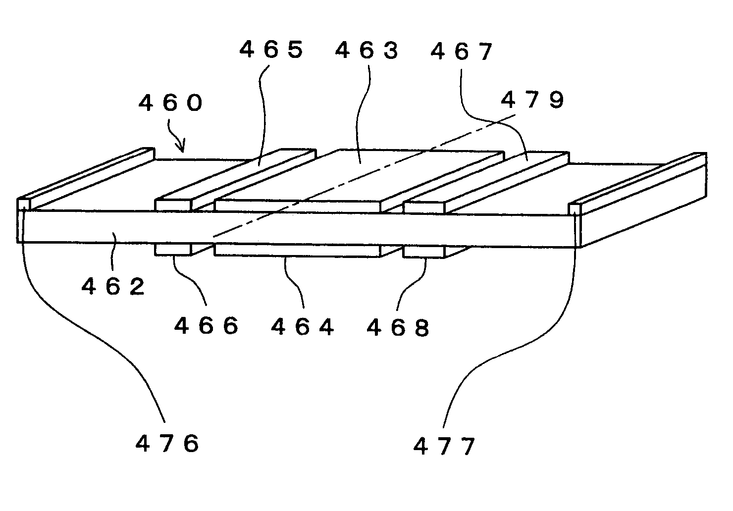
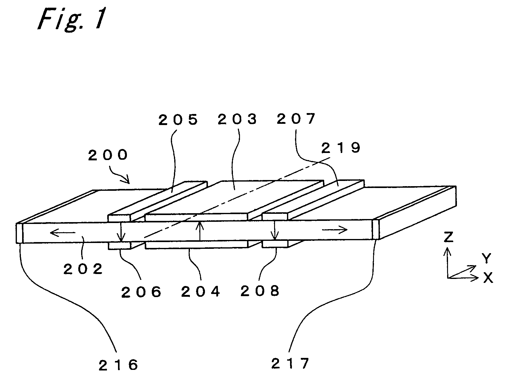
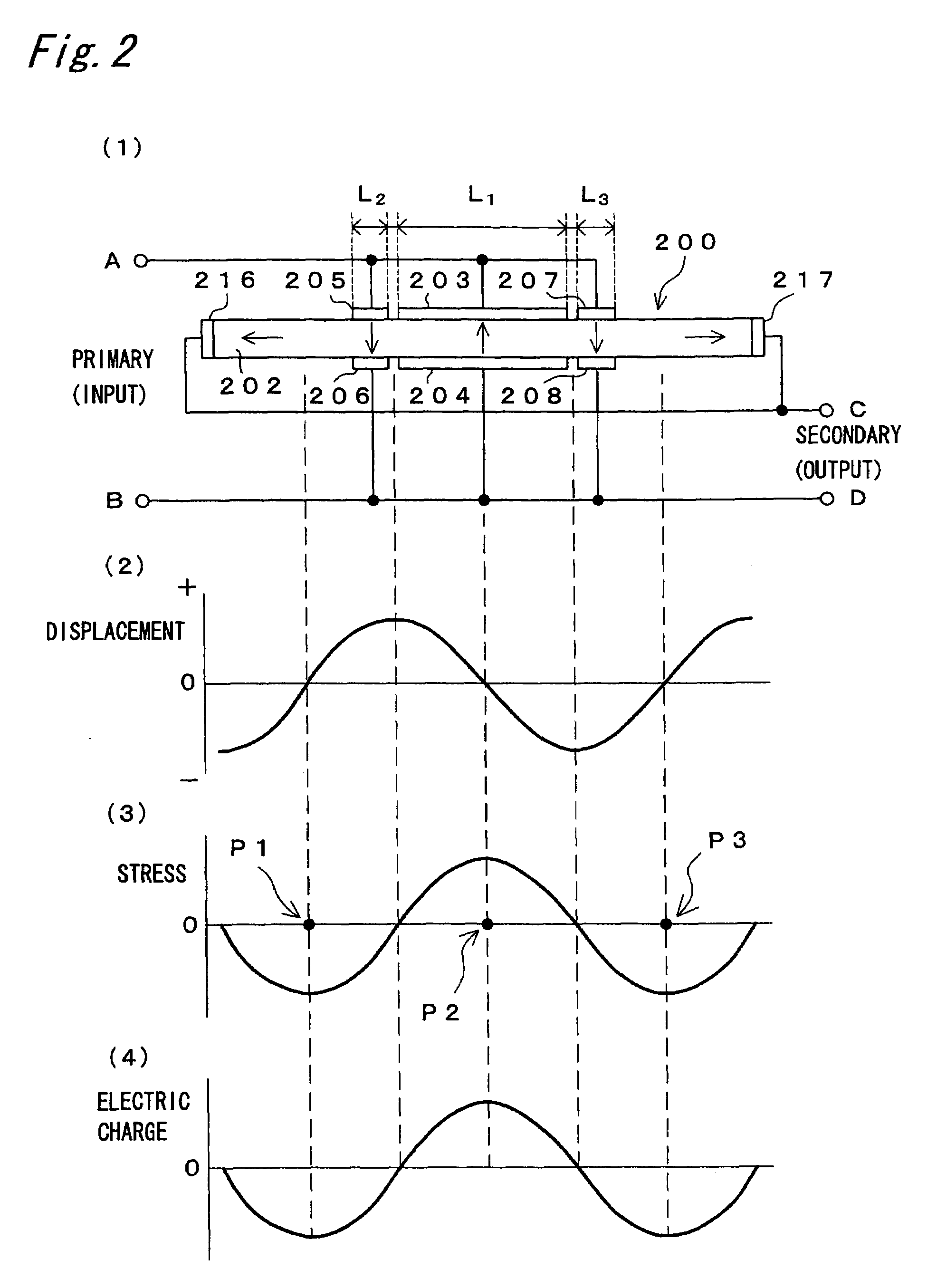
[0140]FIG. 1 is a perspective view of a piezoelectric transformer having the 3λ / 2 longitudinal extensional vibration mode according to the first embodiment of the present invention. FIG. 2(1) is a side view of the piezoelectric transformer shown in FIG. 1. In FIGS. 1 and 2(1), the piezoelectric transformer 200 includes a rectangular plate 202 made of a piezoelectric material. First, the directions of the rectangular plate 202 will be defined using an orthogonal coordinate system shown in FIG. 1. It is defined that the longitudinal direction, width direction and thickness direction of the rectangular plate 202 indicate respectively an x axis direction, a y axis direction and a z axis direction in the orthogonal coordinate system shown in FIG. 1. This definition applies to all piezoelectric transformers to be described later. Further, in the following description, a length simply means the length of a rectangular plate in the longitudinal direction thereof. A length in the width direc...

second embodiment

[0162]FIG. 6 is a perspective view of a piezoelectric transformer having the 3λ / 2 longitudinal extensional vibration mode according to the second embodiment of the present invention. FIG. 7(1) is a side view of the piezoelectric transformer shown in FIG. 6. In FIGS. 6 and 7(1), the piezoelectric transformer 220 includes a rectangular plate 222 made of a piezoelectric material. Primary (input) electrodes are formed on two main surfaces of the rectangular plate 222 perpendicular to the thickness direction thereof. The primary electrodes consisting of electrodes 223, 225 and 227 are formed on one of the two main surfaces and the other primary electrodes consisting of electrodes 224, 226 and 228 are formed on the other main surface. In addition, the center line of each of the electrodes 223 and 224 substantially coincides with the center line 239 of the rectangular plate 222. The electrodes 223 and 224, the electrodes 225 and 226 and the electrodes 227 and 228 are formed to be opposed e...

third embodiment

[0175]FIG. 8 is a perspective view of a piezoelectric transformer having the 3λ / 2 longitudinal extensional vibration mode according to the third embodiment of the present invention. FIG. 9(1) is a side view of the piezoelectric transformer shown in FIG. 8. In FIGS. 8 and 9(1), the piezoelectric transformer 240 includes a rectangular plate 242 made of a piezoelectric material. Primary (input) electrodes consisting of a plurality of electrodes in the length and thickness directions of the rectangular plate 242 are formed near the central portion of the rectangular plate 242 in the longitudinal direction thereof. Primary electrodes have multilayer structures in which piezoelectric layers made of piezoelectric material such as piezoelectric ceramic and internal electrode layers made of metal material are alternately layered.

[0176]In FIG. 9(1), five piezoelectric layers and four electrode layers are present between two electrodes, which are components of the primary electrodes, opposed e...


PUM

PropertyMeasurementUnit
frequencyaaaaaaaaaa
voltageaaaaaaaaaa
thicknessaaaaaaaaaa

Abstract

A compact and high-power piezoelectric transformer is realized by using higher order longitudinal extensional mode vibrations and increasing an effective electromechanical coupling factor by a primary electrode which consists of plural electrodes.

Description

[0001]This application is a divisional application of application Ser. No. 10 / 253,757, filed Sep. 23, 2002, now U.S. Pat. No. 6,812,623.BACKGROUND OF THE INVENTION[0002]1. Field of the Invention[0003]The present invention relates to a piezoelectric transformer which transforms the amplitude of an alternating voltage by the piezoelectric effect of a piezoelectric material such as a piezoelectric ceramic.[0004]2. Description of the Related Art[0005]A piezoelectric transformer which was designed for a step-up transformer of a high voltage power supply has not been commercialized because of limited properties of a piezoelectric ceramic material such as breaking strength. However, with the advance of high strength piezoelectric ceramics, attention has been recently paid again to the piezoelectric transformer as the step-up transformer for an inverter of a backlight source of the liquid crystal display (LCD) panel installed on a portable information equipment, in the face of the increasin...

Claims


Application Information

Patent Timeline
Patent Type & Authority Patents(United States)
IPC IPC(8): H01L41/107H05B41/282
CPCH05B41/2822H01L41/107H10N30/40
Inventor TAKEDA, KATSUNAKATSUKA, HIROSHIYAMAGUCHI, TAKESHIOKUYAMA, KOJIROMORITOKI, KATSUNORI
Owner PANASONIC CORP
Learn More