
Fuel filter with restriction indicator, and method of using same

a technology of restriction indicator and fuel filter, which is applied in the direction of cartridge filter, filtration separation, separation process, etc., can solve the problems of reducing engine performance and premature engine wear, affecting combustion efficiency, and not always appearing visually different plugged filter elements, etc., to reduce or eliminate microbial growth, stabilize fuel quality, and improve combustion

Active Publication Date: 2006-01-24
BMO HARRIS BANK N A AS SUCCESSOR COLLATERAL AGENT +1
View PDF12 Cites 11 Cited by
  • Summary
  • Abstract
  • Description
  • Claims
  • Application Information

AI Technical Summary

Benefits of technology

[0013]A filter element according to the invention may include a hydrophobic filter media, to remove fuel contaminants from fuel, and to reduce or eliminate microbial growth within the downstream components of a vehicle's fuel system.
[0014]Additionally, the fuel filter hereof may also contain one or more fuel additives, for slow release over time, to stabilize fuel quality, improve combustion, reduce emissions, clean fuel injectors, etc. Examples of some fuel additives which may be associated with the fuel filter hererof include antioxidants, cetane improvers, corrosion inhibitors, demulsifiers, dispersants, lubricating agents, metal detergents, and metal deactivators coated with a hydrocarbon-insoluble material.
[0015]The fuel filter according to the invention may include a restriction indicator gauge for fuel flow through in-situ analysis. In-situ analysis visually and beneficially indicates the actual level of restriction applied to fuel flowing to the engine. Such an in-situ fuel flow restriction indicating device is advantageous because the indicator may also be retrofitted on to a conventional fuel filter housing equipped with a drain plug. This capability permits vehicle owners of nearly all makes and models to reap the benefits of visual fuel restriction detection, which helps preserve the life of a vehicle's engine. This feature of the device also affords a cost-effective mechanism for sensing fuel restriction, as it requires no specifically designated mounting area and no separate maintenance. A worn system may be replaced with a new system as part of a new fuel filter installation, as required.

Problems solved by technology

In particular, fuel filters protect the engine from contaminants, such as dirt and water which, if left unfiltered, could result in inefficient combustion, reduced engine performance and premature engine wear.
However, visually determining when to replace a filter, based upon this known method is subjective, given that filter replacement depends on the opinion and / or experience of the individual viewing the filter.
Moreover, a plugged filter element does not always appear visually different from a clean one.
Accordingly, concerns arise on both sides as to when a fuel filter should be replaced; premature replacement of a fuel filter gives rise to cost, disposal, and environmental concerns, while delayed replacement of a fuel filter gives rise to concerns of diminished engine performance, reduced efficiency and premature wear.

Method used


Image

  • Fuel filter with restriction indicator, and method of using same
  • Fuel filter with restriction indicator, and method of using same
  • Fuel filter with restriction indicator, and method of using same

Examples


first embodiment

[0021]Overview—First Embodiment

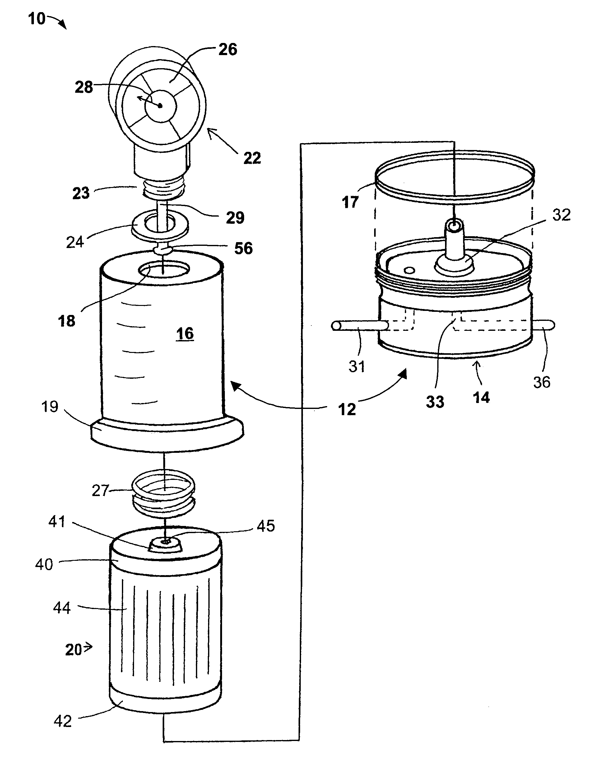
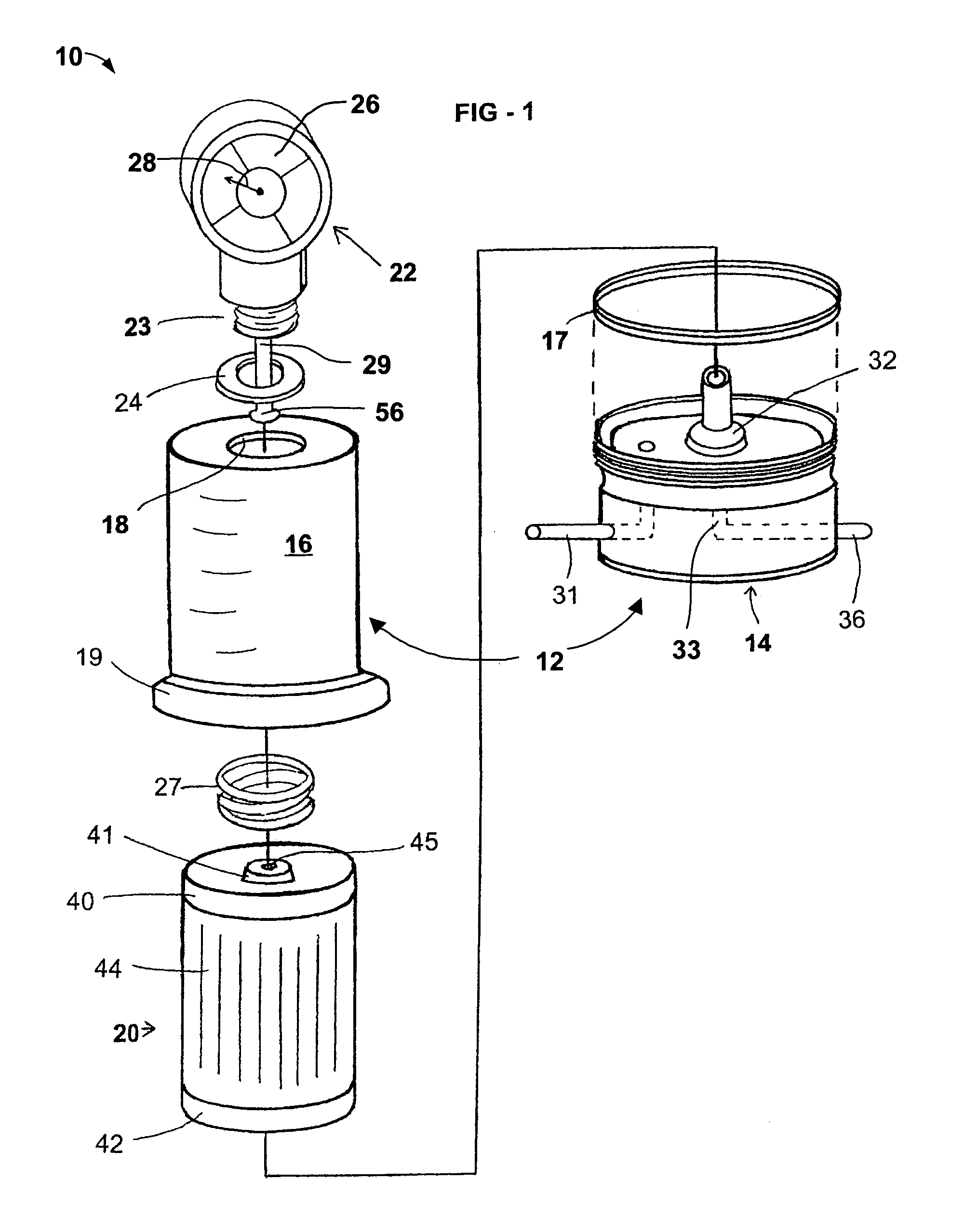
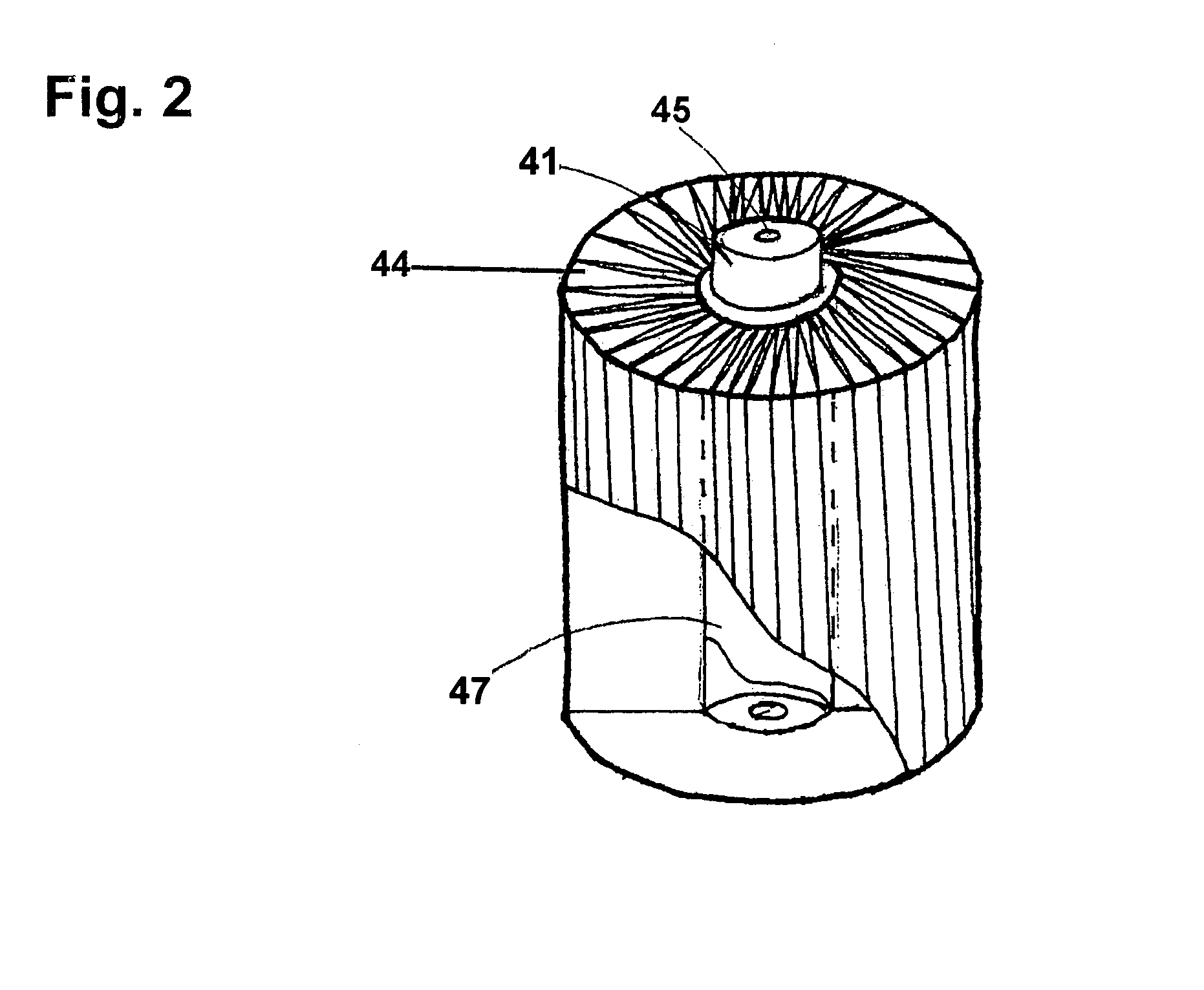
[0022]Referring now to FIGS. 1–2, a fuel filter assembly and restriction indicating system, in accordance with the present invention, is shown generally at 10. The assembly 10 includes a two-part housing 12 (FIG. 2), a filter element 20 disposed within the housing, and a restriction indicator gauge 22, which fits into a threaded opening in the housing, as will be further described. Other secondary parts are also included, as will be further described herein.

[0023]The Filter Housing

[0024]The housing 12 includes a base 14 having a plurality of channels formed therein, and a housing cover 16, which fits threadably and rotatably on top of the base. A lower O-ring seal 17 is provided for sealing placement between the base 14 and the housing cover 16.

[0025]The housing cover 16 may be constructed from material similar to conventional, transparent fuel filter housings; however, since the housing cover need not be transparent, it may be constructed from any mat...

second embodiment

[0046

[0047]Referring now to FIG. 3, a modified fuel filter assembly according to a second embodiment of the invention is shown generally at 100. The filter assembly 100 according to this embodiment shares many features with the first embodiment. Unless specifically described as different herein, it will be understood that the filter assembly 100 is similar to the filter assembly 10 as previously described.

[0048]The filter assembly 100 according to the second embodiment includes a restriction sensor 122 in place of the gauge 22 used in the first embodiment. The sensor 122 includes electrical contacts 130 for connecting to a plug connector 132, to send a signal to a remote location.

[0049]If desired, the plug connector may place the sensor 122 into communication with the main vehicle computer, such as the powertrain control module or the like.

[0050]Preferably, the signal from the sensor 122 is sent as a digital signal, and the wire(s) 133 going to the connector 132 either carry no curr...


PUM

PropertyMeasurementUnit
pressureaaaaaaaaaa
flexibleaaaaaaaaaa
transparentaaaaaaaaaa

Abstract

A fuel filter assembly for a combustion engine, including a two-part filter housing, a filter element, and a restriction sensor, including an external visual display apparatus for indicating when to replace the filter element. As fluid pressure increases within the filter housing, the visual display apparatus correspondingly displays the increase in pressure. When the pressure sensor detects an amount of pressure at or in excess of a predetermined amount, the visual display apparatus indicates replacement of the filter element. A modified embodiment including an electronic pressure sensor and a remote display unit is also described.

Description

BACKGROUND OF THE INVENTION[0001]1. Field of the Invention[0002]The present invention relates to a fuel filter apparatus for filtering contaminants from liquid fuel for combustion engines, including an indicator for displaying the condition of the filter media contained therein, and to methods of using the described apparatus. More particularly, the present invention relates to a fuel filter including a restriction indicator gauge with a visual display, for identifying when a fuel filter needs to be replaced, and to methods of using the described filter.[0003]2. Description of the Background Art[0004]The use of fluid filters to protect the downstream components of a machine is well known. Several different fluids associated with internal combustion engines require filtration, i.e. fuel and oil. In particular, fuel filters protect the engine from contaminants, such as dirt and water which, if left unfiltered, could result in inefficient combustion, reduced engine performance and prem...

Claims


Application Information

Patent Timeline
Patent Type & Authority Patents(United States)
IPC IPC(8): C02F1/00B01D35/143
CPCB01D35/143
Inventor REAMSNYDER, CHRISTOPHER R.LOGAN, DARRYL V.
Owner BMO HARRIS BANK N A AS SUCCESSOR COLLATERAL AGENT
Learn More