Oil cooler and small watercraft
a technology for oil coolers and watercraft, which is applied in the direction of steam power plants, motor-driven power plants, lubricant mounting/connection, etc., can solve the problems of difficult to achieve a lightweight small watercraft, complex piping configuration, and unsuitability for use, and achieves simple piping configuration and easy maintenance
- Summary
- Abstract
- Description
- Claims
- Application Information
AI Technical Summary
Benefits of technology
Problems solved by technology
Method used
Image

Examples
embodiment 1
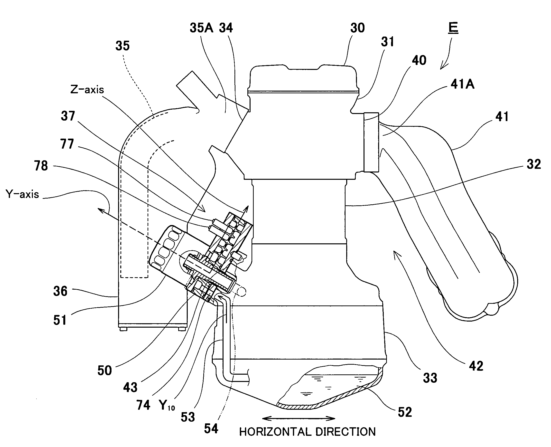
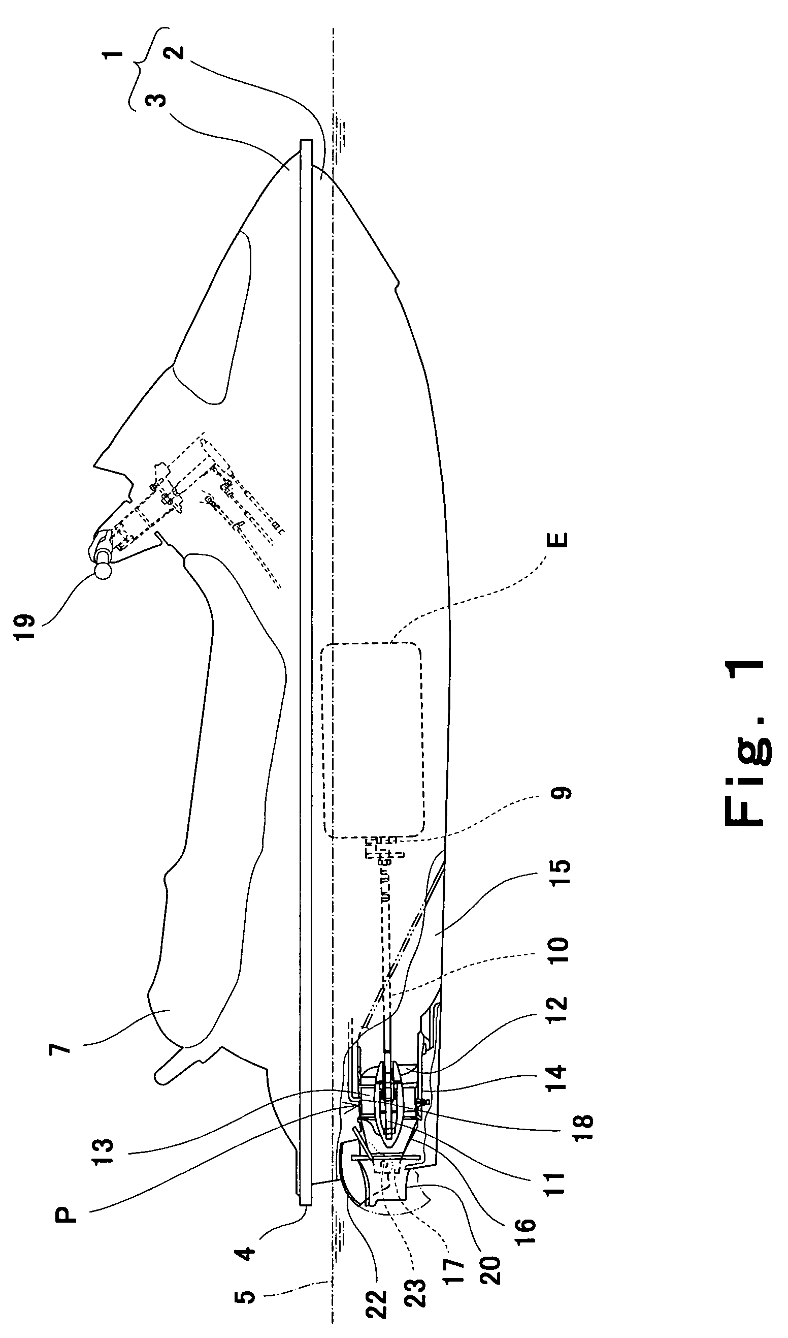
[0077]A first Embodiment of the present invention will be described with reference to FIGS. 3 to 7B. As shown in a side cross-sectional view in FIG. 3, the engine E mainly comprises a cylinder head 31 covered with a cylinder head cover 30 from above, a cylinder block 32 located below the cylinder head 31, and a crankcase 33 located below the cylinder block 32. Four air-intake ports 34 are provided on one side portion of the cylinder head 31 to be spaced equally apart from one other in the longitudinal direction of the engine E. The air-intake ports 34 open toward a lateral side of the engine E. One end portions 35A of air-intake pipes 35 are respectively connected to the air-intake ports 34.
[0078]As shown in FIG. 4, each of the air-intake pipes 35 extends from the corresponding air-intake port 34 toward outer side of the engine E. Then, the air-intake pipe 35 is curved downwardly at a position thereof and then extends to a position lateral of the crankcase 33. As shown in FIG. 3, op...
embodiment 2
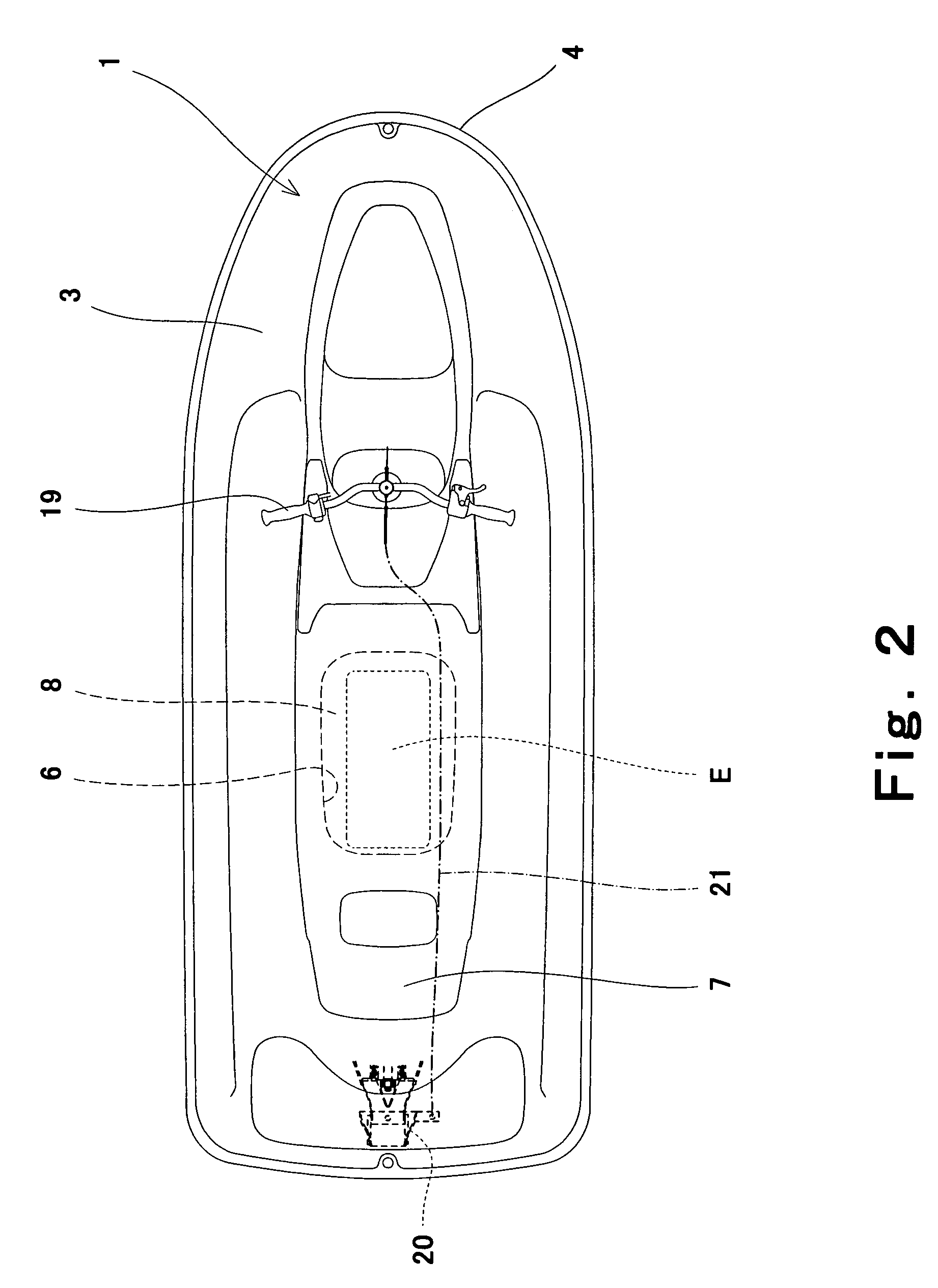
[0103]An oil cooler having another configuration will be described with reference to FIGS. 8 to 11. In FIGS. 8 to 11, the same reference numerals as those in FIGS. 1 to 7 denote the same or corresponding parts. The oil cooler of this embodiment is applicable to the personal watercraft described with reference to FIGS. 1 and 2. As shown in a side view of the engine E in FIG. 8, an oil cooler 80 is provided within the space 37 between the air-intake pipe 35 and the crankcase 33, as in the oil cooler 50 of the first embodiment.
[0104]As shown in a front view of the oil cooler 80 in FIG. 9, the oil cooler 80 is substantially rectangular. The oil cooler 80 is provided with a joint 81 and a joint 82 at a forward end portion thereof. The cooling water flows into the oil cooler 80 through the joint 81 and flows out of the oil cooler 80 through the joint 82. The ends of the tubes 72 are connected to the joints 81 and 82, respectively. The oil filter 51 is attached on a front face of the oil c...
embodiment 3
[0114]An oil cooler having another configuration will be described with reference to FIGS. 12 to 19. The oil cooler of this embodiment is applicable to the personal watercraft described with reference to FIGS. 1 and 2.
[0115]Referring to FIG. 12, an oil cooler 100 of this embodiment comprises a number of passage forming plates formed by casting using metal such as aluminum between the rear-face cover plate 101 and the front-face cover plate 102. The oil cooler 100 of this embodiment has a two-layered structure comprising two stacked pairs of plates, each pair having an oil passage forming plate 103 and a cooling water passage forming plate 104. The passage forming plate 103 forms the oil passage 105 and the cooling water passage forming plate 104 forms the cooling water passage 106.
[0116]Referring to FIGS. 13A to 13C, the rear-face cover plate 101 has a predetermined thickness. A cooling water passage groove 111 is formed to extend sinuously on a front face of the rear-face cover pla...
PUM
 Abstract
Description
Claims
Application Information
 - R&D
- Intellectual Property
- Life Sciences
- Materials
- Tech Scout
- Unparalleled Data Quality
- Higher Quality Content
- 60% Fewer Hallucinations
Browse by: Latest US Patents, China's latest patents, Technical Efficacy Thesaurus, Application Domain, Technology Topic, Popular Technical Reports.
© 2025 PatSnap. All rights reserved.Legal|Privacy policy|Modern Slavery Act Transparency Statement|Sitemap|About US| Contact US: help@patsnap.com