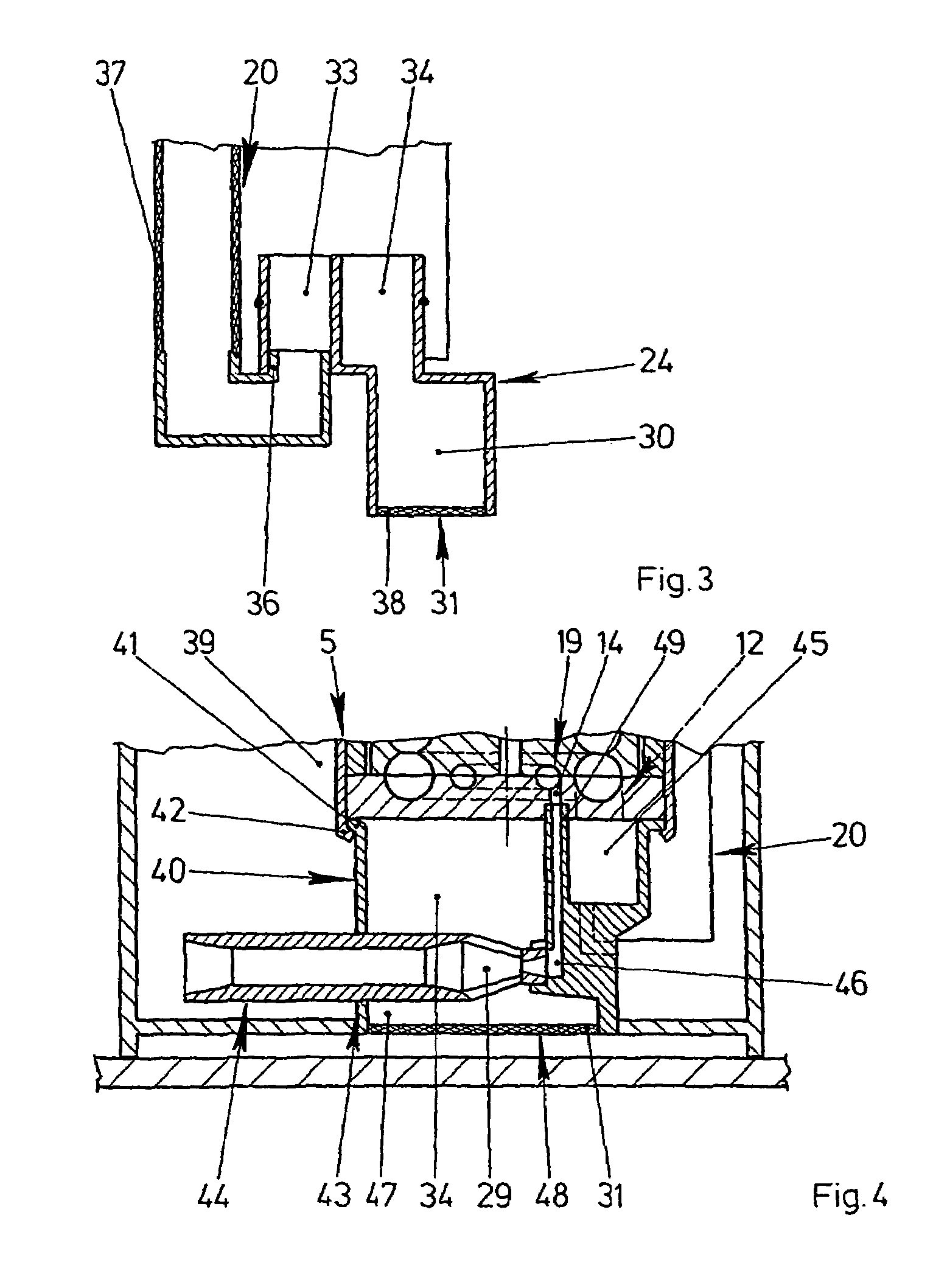
Pump unit arranged in an inner tank of a fuel tank of a motor vehicle

a technology of a fuel tank and a pump unit, which is applied in the direction of liquid fuel feeders, machines/engines, transportation and packaging, etc., can solve the problems of inability to combine individual sub-assemblies and complex construction, and achieve the effect of avoiding flow losses, ensuring stability, and ensuring the connection of the housing part to the fuel pump

Inactive Publication Date: 2006-01-24
CONTINENTAL AUTOMOTIVE GMBH
View PDF19 Cites 20 Cited by
  • Summary
  • Abstract
  • Description
  • Claims
  • Application Information

AI Technical Summary

Benefits of technology

[0009]Separate manufacturing of the ejector pump and housing part is generally required if the pump unit is provided for different surge chambers and fuel tanks. The pre-assembly of the pump unit according to the invention becomes particularly simple during the separate manufacturing of the housing part if the housing part contains the ejector pump or has a holder for the ejector pump or of a subregion of the ejector pump.
[0010]According to another advantageous development of the invention, the connection of the housing part to the fuel pump is highly stable if the housing part has an annular flange which is prestressed against the fuel pump. Furthermore, the housing part thereby requires a particularly small amount of material to be used.
[0011]The housing part could, for example, be rolled together with a housing part, which is manufactured from sheet metal, of the fuel pump. However, according to another advantageous development of the invention, the assembly and the removal of the housing part become particularly simple if the housing part has a plug-in connection on the fuel pump.
[0012][lacuna] inlet and outlet regions arranged very close to one another. However, in order to avoid flow losses, the inlet regions generally have to be very large. The pump unit according to the invention has very low flow losses and turns out to be particularly compact if the channel of the working-fluid line of the ejector pump has a pipe length which is guided to the fuel pump through a connecting branch which has the inlet region.

Problems solved by technology

A disadvantage of the known pump unit is that it is of very complex construction and pre-assembly to form individual subassemblies which can be combined with one another is not possible.

Method used


Image

  • Pump unit arranged in an inner tank of a fuel tank of a motor vehicle
  • Pump unit arranged in an inner tank of a fuel tank of a motor vehicle
  • Pump unit arranged in an inner tank of a fuel tank of a motor vehicle

Examples


Embodiment Construction

[0019]FIG. 1 shows a bottom region of a fuel tank 1 of a motor vehicle with a pump unit 2 inserted therein. The pump unit 2 comprises a surge chamber 3 with a fuel pump 5 which is driven by an electric motor 4. The fuel pump 5 has an impeller 8 which is arranged between two fixed housing parts 6, 7 and can be driven by the electric motor 4. Two rings of vane chambers 9–11 are arranged in the impeller 8. In the region of the vane chambers 9–11, the housing parts 6, 7 have partially annular channels 15–17 which extend in each case from an inlet region 12 to an outlet region 13, 14. The partially annular channels 15–17 form with the vane chambers 9–11 pump chambers 18, 19 for pumping the fuel. Since radially outer vane chambers 9, 10 which lie opposite each other merge into one another, the flow passes axially through the impeller 8 in this region. The fuel pump 5 is therefore designed as a side-channel pump. During rotation of the impeller 8, fuel is sucked out of the surge chamber 3 ...


PUM


Abstract

The invention relates to a pump unit arranged in an inner tank (3) of a fuel tank, comprising a fuel pump (5) which is used to pump fuel to the internal combustion engine of a motor vehicle; an ejector pump (21) which is connected to the fuel pump (5) and used to pump fuel out of the fuel tank into the inner tank (3); and at least one filter element (20:31) which is used to filter fuel, wherein a housing part which is connected to the fuel pump (5) is provided with at least one channel (30;33;35;47) for guiding said fuel. In order to simplify the structure of the pump unit (2) and to enable substantial pre-assembly, the housing part (24;40) is configured in such a way that it can hold the at least one filter element (20;31), and the channel (30;33;35;47) is exclusively guided inside the housing part (24; 40) from the ejector pump (21) and/or the fuel pump (5) to the filter element (20;31).

Description

BACKGROUND OF THE INVENTION[0001]The invention relates to a pump unit which is to be arranged in a surge chamber of a fuel tank of a motor vehicle, having a fuel pump which is provided for pumping fuel to an internal combustion engine of the motor vehicle, having an ejector pump which is connected to the fuel pump and is used to pump fuel out of the fuel tank into the surge chamber, and having at least one filter element for filtering fuel, a housing part which is connected to the fuel pump having at least one channel which is provided for guiding the fuel.[0002]Pump units of this type are frequently used in motor vehicles today and are known from practice. The housing part of the known pump unit has a flange with which it is inserted into a recess of the surge chamber and is sealed with respect to the latter. The channel leading to the intake side of the ejector pump is guided as far as the flange. The filter element is fastened on the lower side of the surge chamber and has an edg...

Claims


Application Information

Patent Timeline
Patent Type & Authority Patents(United States)
IPC IPC(8): F02M37/04B60K15/077F02M37/02F02M37/10
CPCB60K15/077F02M37/106F02M37/025B60K2015/03111B60K2015/03236B60K2015/03105
Inventor BURHENNE, SABINEDEICHMANN, JOHANNESDEUBNER, JOERGMARX, PETEROSBURG, HANS-PETER
Owner CONTINENTAL AUTOMOTIVE GMBH
Why Eureka
Try Eureka