Kneepad
- Summary
- Abstract
- Description
- Claims
- Application Information
AI Technical Summary
Benefits of technology
Problems solved by technology
Method used
Image
Examples
Embodiment Construction
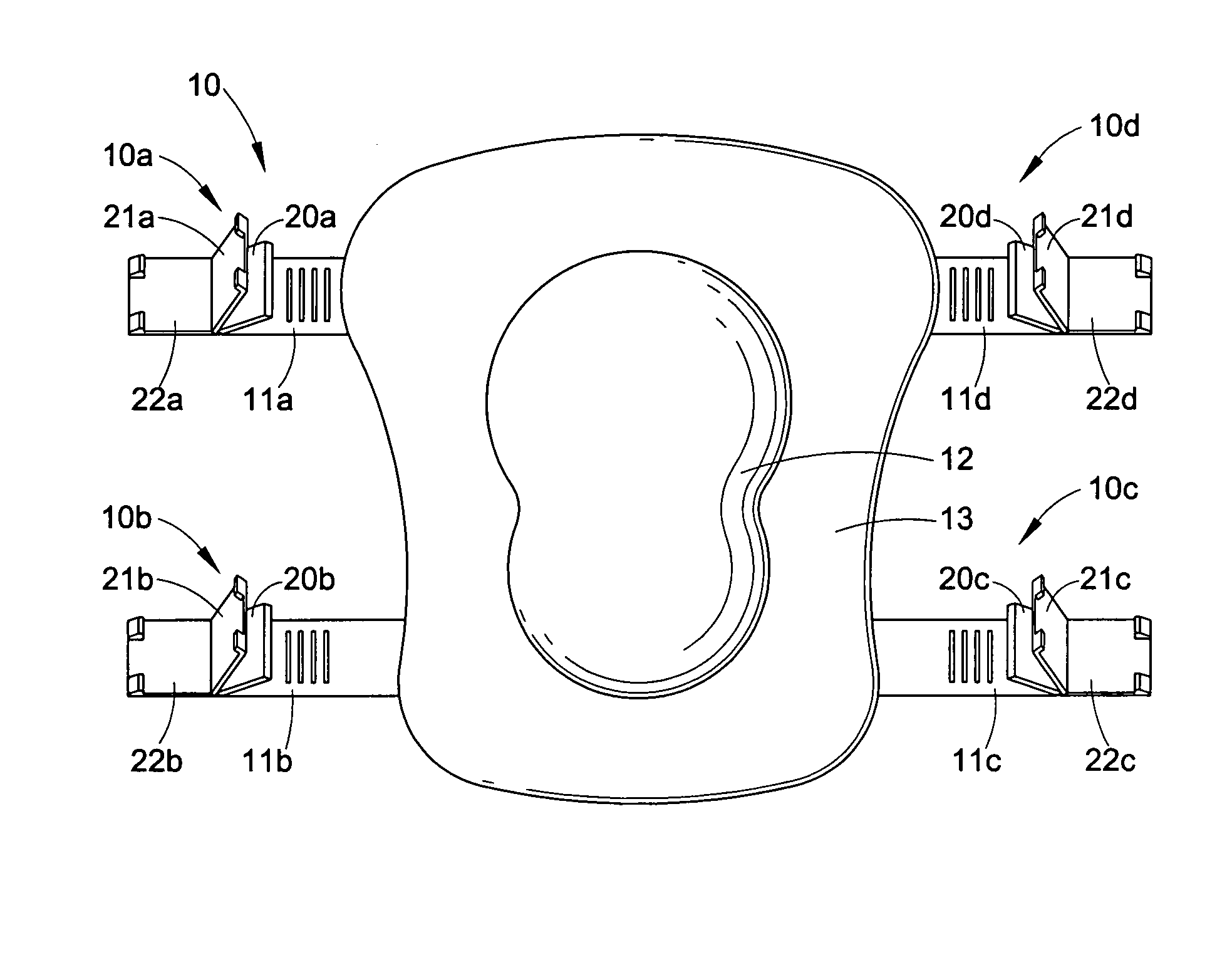
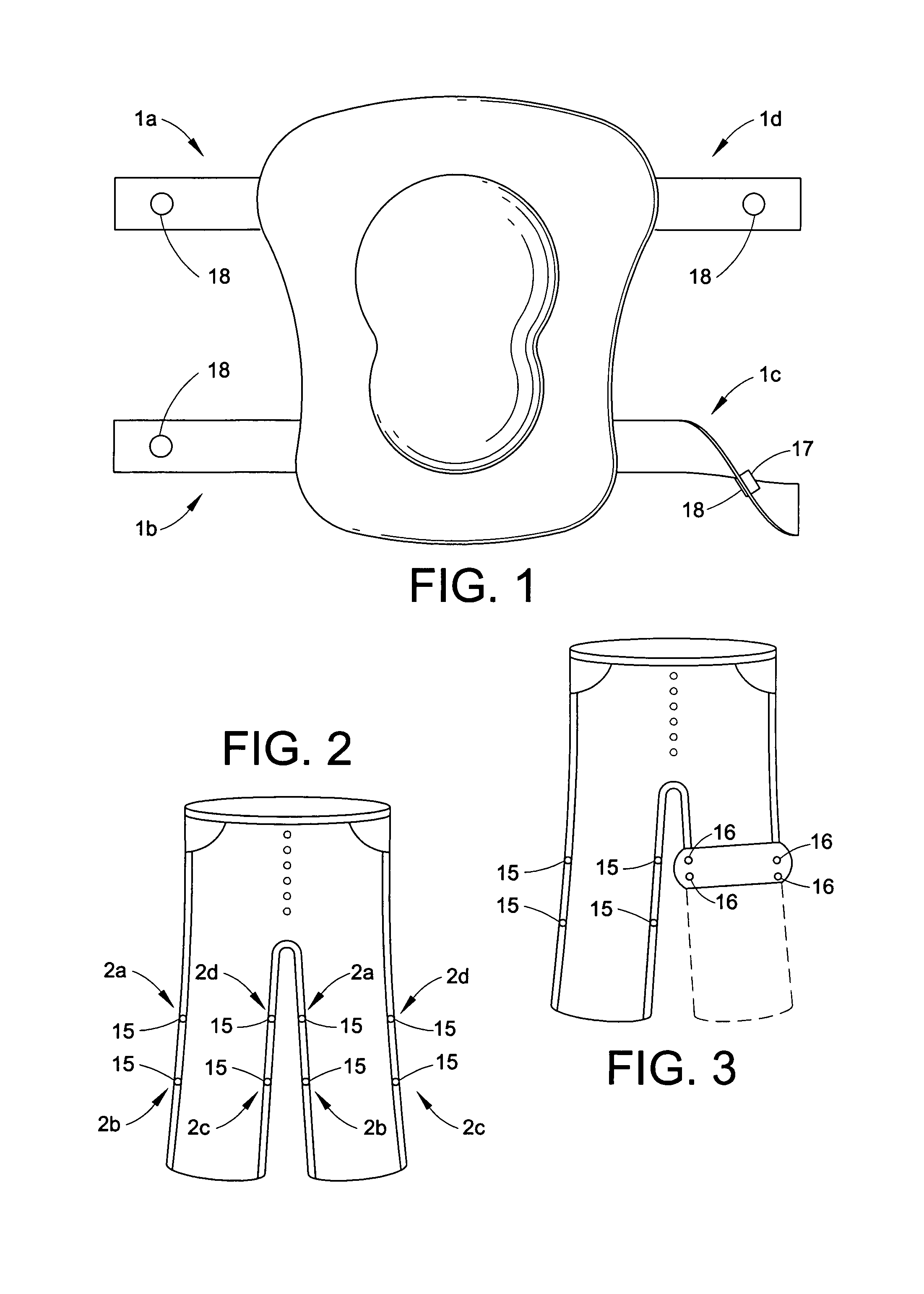
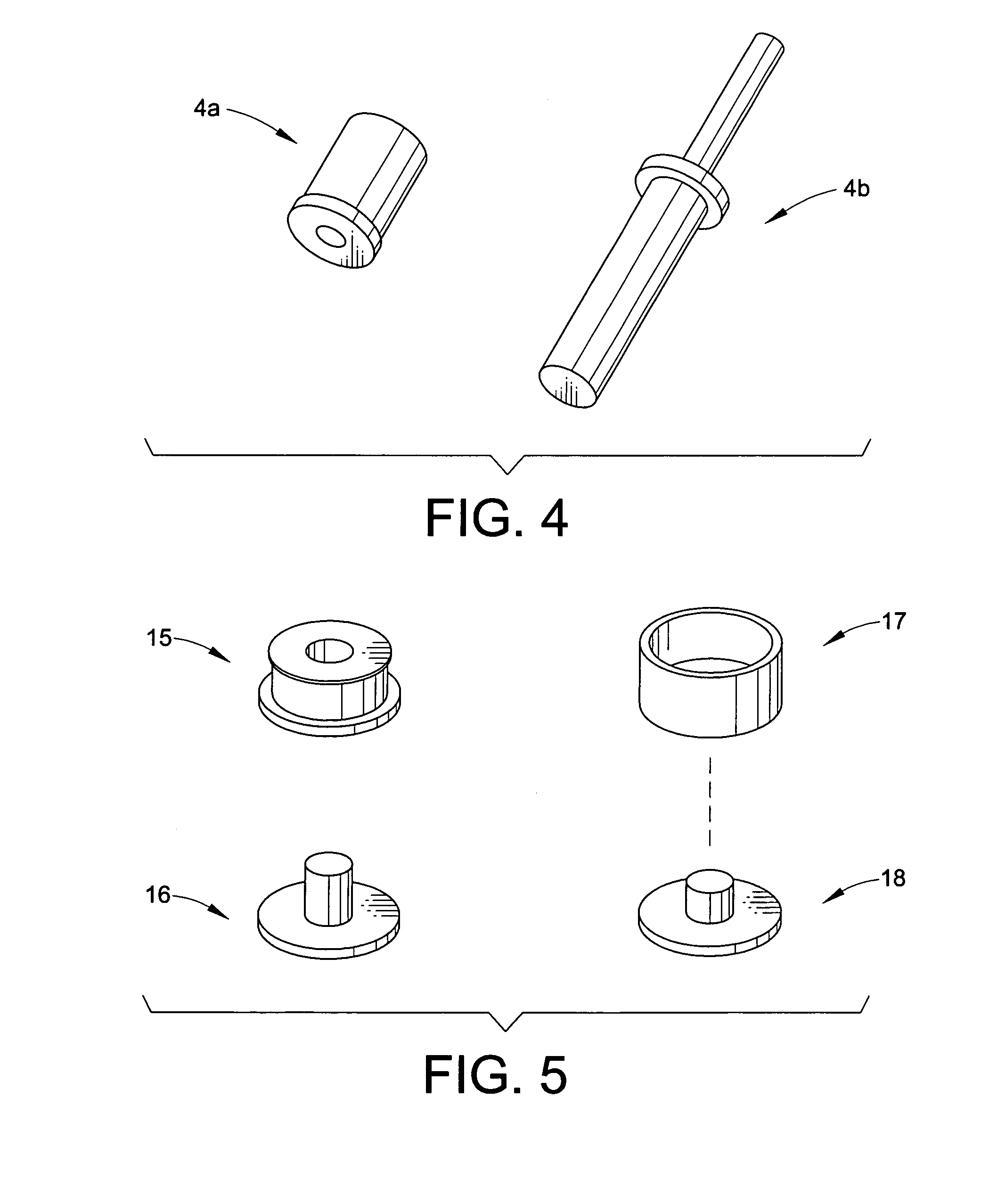
[0033]Referring now to the drawing. FIG. 1 is the frontal view of an existing kneepad with four straps or appendages, one on each corner, which will conform to the invention. Area 1a is the approximate location for applying fasteners 17 and fasteners 18. Area 1b is the approximate location for applying fasteners 17 and fasteners 18. Area 1c is the approximate location for applying fasteners 17 and fasteners 18. Area 1d is the approximate location for applying fasteners 17 and fasteners 18. Where fastener 17 penetrates from the under side of the kneepad strap and fastener 18 mates to it from the outside of the kneepad strap to make a permanent kneepad coupling device.
[0034]It should be noted that the hardware comprising of 17, and 18 can consist of many different types of firm material such as steel, brass, plastic, and the like. Also, it can be decorative in colors and covered with fabrics or in a military finish to blend and or match the pad.
[0035]Another example of the Invention, ...
PUM
 Abstract
Description
Claims
Application Information
 - R&D
- Intellectual Property
- Life Sciences
- Materials
- Tech Scout
- Unparalleled Data Quality
- Higher Quality Content
- 60% Fewer Hallucinations
Browse by: Latest US Patents, China's latest patents, Technical Efficacy Thesaurus, Application Domain, Technology Topic, Popular Technical Reports.
© 2025 PatSnap. All rights reserved.Legal|Privacy policy|Modern Slavery Act Transparency Statement|Sitemap|About US| Contact US: help@patsnap.com


