
Liquid/solid separator and method

Inactive Publication Date: 2006-01-17
ENG FLUID SOLUTIONS
View PDF18 Cites 23 Cited by
  • Summary
  • Abstract
  • Description
  • Claims
  • Application Information

AI Technical Summary

Benefits of technology

[0004]One embodiment of the invention involves a unique design that significantly reduces the consumption rate of fluids used in industrial processes while largely optimizing, balancing and mitigating the aforementioned operational- and maintenance-related efficiencies. The design integrates four (4) distinct separation elements that are optimally arranged to achieve desired results:

Problems solved by technology

Many industries consume large volumes of fluids (predominately water), chemical additives and reagents in manufacturing products.
Excess solid debris loosely adhering to newly manufactured or remanufactured products is washed off in rinsing / spraying processes and accumulates in short order in reservoirs of immersion and spray waters, which degrades the cleansing ability of the fluid, leaving it ineffective in achieving desired product quality.
A significant cost burden is associated with up-front purchasing, inventorying and administration in re-supplying fresh fluids and additives, which is furthered in properly treating (physically, chemically & biologically) used fluids before discharging to the environment for natural recycling.
At present, conventional approaches to solving and / or mitigating the aforementioned problem are fraught with inefficiencies that include: 1) high initial capital equipment cost; 2) difficulty in installation and mobilization of equipment; 3) difficulty in understanding and controlling operation; 4) requirements for formal training to operate and maintain; 5) difficulty in troubleshooting; 6) high frequency wear parts and many moving parts; 7) requirements for specialty tools in operating and maintaining; 8) large, heavy and extensive (large footprint); 9) high incremental cost in replacing consumable filtration media; 10) strict physical property requirements of accumulating solids in specific gravity, size, shape, consistency and character; 11) high associated maintenance time and cost; 12) pressure- and flow-sensitive; 13) limited scope by relying largely on a single principal of operation; 14) low efficiency; 15) undesirable interruption of main process when maintaining; 16) frequent and voluminous discharge and flush volumes required during automatic cleaning cycles; 17) largely non-automatic in cleaning internal elements; 18) high associated energy cost; 19) difficulty in accessing and maintaining internal elements; 20) frequent malfunction; 21) frequent obstruction of critical elements; 22) auxiliary power requirements and controls in initiating auto-cleaning modes; 23) sharing of filtration equipment between reservoir tanks is prohibitive due to conventional design mindset around a necessarily permanent configuration; 24) filtration equipment typically does not come fully packaged, requiring integration of ancillary equipment, controls and instrumentation; 25) replacement of internal elements in determining ideal media pore sizes is expensive and time-consuming; 26) units are easily tampered with; 27) high shipping and handling costs on weight and volume basis; 28) degree of influence in removing solids from fluids is not appreciable (rate of fluid contamination is appreciably greater than rate of solids removal); 29) disassembly is time-consuming, difficult and potentially unsafe; 30) low return on investment translating into long payback periods; 31) operational results selfishly favoring either business perspective or environmental perspective; and 32) that problem is not truly solved, rather, it is transferred.

Method used


Image

  • Liquid/solid separator and method
  • Liquid/solid separator and method
  • Liquid/solid separator and method

Examples


Embodiment Construction

[0023]For the purposes of promoting an understanding of the principles of the invention, reference will now be made to the embodiments illustrated in the drawings and specific language will be used to describe the same. It will nevertheless be understood that no limitation of the scope of the invention is thereby intended, such alterations and further modifications in the illustrated devices, and such further applications of the principles of the invention as illustrated therein being contemplated as would normally occur to one skilled in the art to which the invention relates.

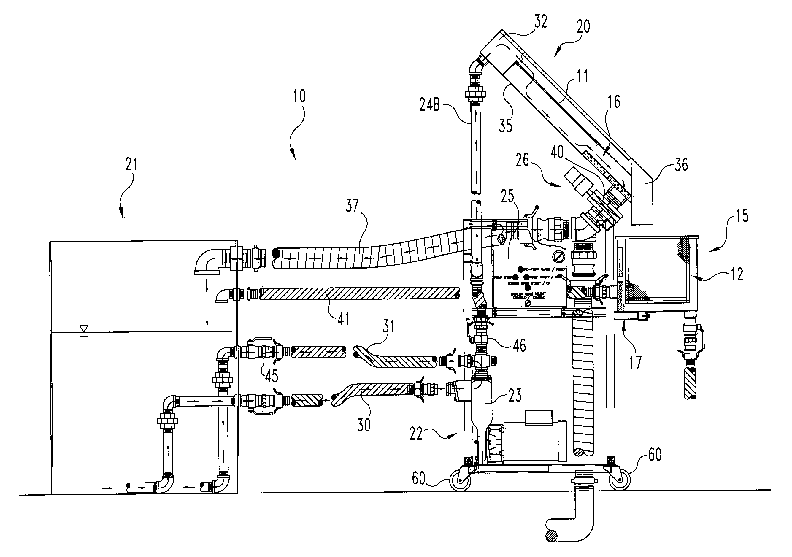
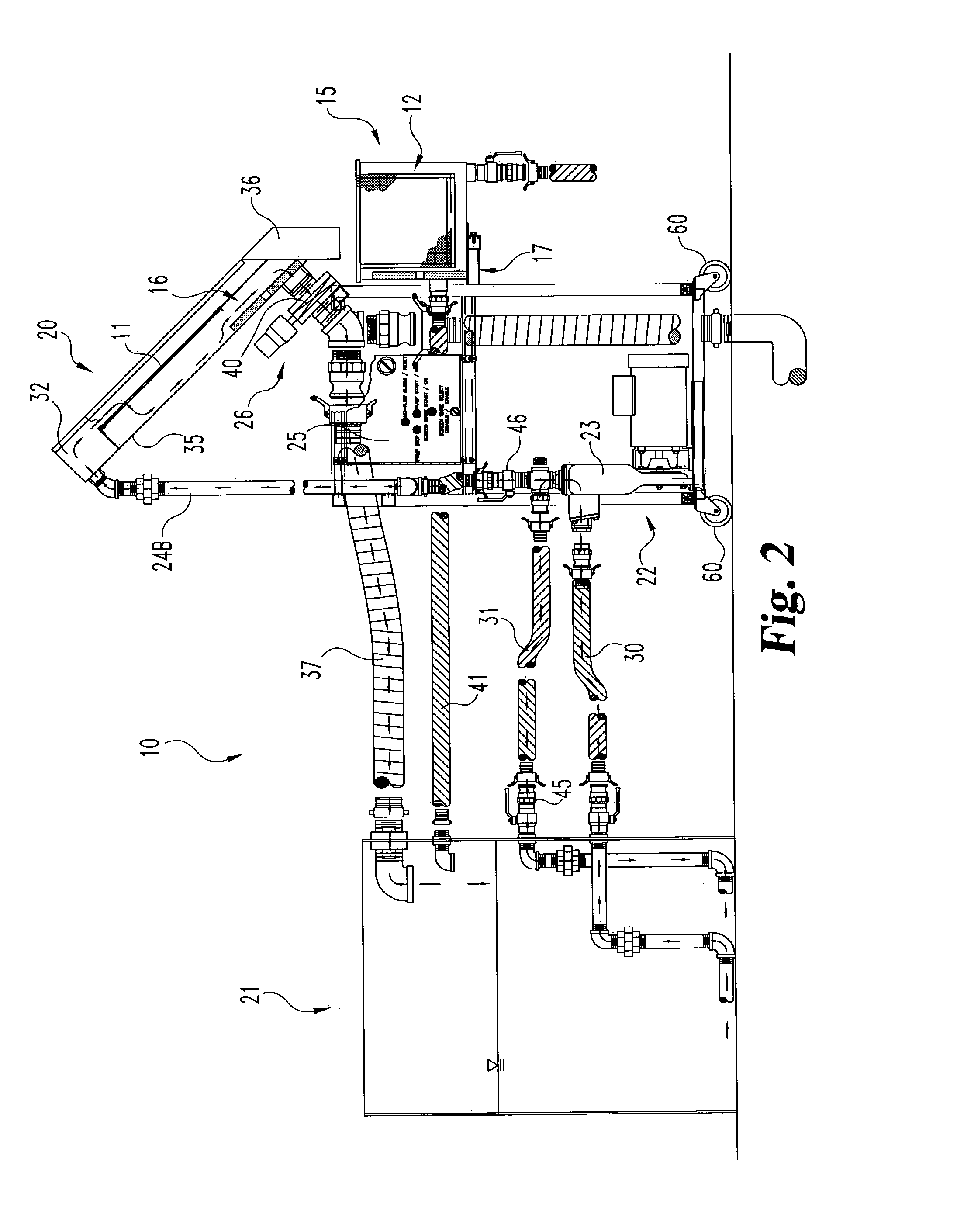
[0024]Referring to the drawings and particularly to FIG. 2, there is illustrated an apparatus 10 that includes four separation elements. The primary separation element is a tilted wire wedge-wire coarse screen 11. The secondary separation element is a woven wire mesh fine screen 12. The tertiary separation element is a settling box 15 and the quaternary separation element is magnets 16 and 17. These four eleme...


PUM

PropertyMeasurementUnit
Angleaaaaaaaaaa
Angleaaaaaaaaaa
Lengthaaaaaaaaaa

Abstract

A liquid / solid separator system mounted on a mobile cart and connected to a process tank for reducing the rate at which fluids are consumed in manufacturing processes. The system may include automation and also may include a shear stepped screen including tilted wire wedge wires arranged at varying cant angles. The system may include a fine screen basket received in a settling box.

Description

FIELD OF THE INVENTION[0001]This invention relates to a liquid / solid separator and method or process.BACKGROUND OF THE INVENTION[0002]Many industries consume large volumes of fluids (predominately water), chemical additives and reagents in manufacturing products. The fluids are used primarily in rinsing, cooling and treatment operations to achieve desired product quality and cleanliness. In industry, manufactured products are often immersion rinsed and / or sprayed several times along an assembly line via immersion tanks and / or high-pressure spray washer conveyors. Excess solid debris loosely adhering to newly manufactured or remanufactured products is washed off in rinsing / spraying processes and accumulates in short order in reservoirs of immersion and spray waters, which degrades the cleansing ability of the fluid, leaving it ineffective in achieving desired product quality. Depending on the manufacturing process, the entire volume (typically between 400 to 2000 gal.) of fluid in an...

Claims


Application Information

Patent Timeline
IPC IPC(8): B01D36/02B01D29/01
CPCB01D21/0006B01D21/0009B01D21/0012B01D29/01B01D36/02B01D29/23B01D29/445B01D29/56B01D29/96B01D29/904B01D36/04C02F2303/24B01D2201/265C02F1/001
Inventor IRVINE, WILLIAM O.
Owner ENG FLUID SOLUTIONS
Learn More