
Apparatus and method for insertion of material in broadcasting

Inactive Publication Date: 2006-01-10
PINNACLE SYST INC A CORP CALIFORNIA +1
View PDF7 Cites 19 Cited by
  • Summary
  • Abstract
  • Description
  • Claims
  • Application Information

AI Technical Summary

Benefits of technology

[0016]The overall object is to achieve an insertion system which allows a flexible and reliable remote control of insertion equipment and which provides reliable timing, cueing, synchronizing and playing of insertion material. A particular object is to provide such a system in a digital implementation, with a high degree of integration of functional units and at a low cost. Another object is to provide a system that utilizes existing broadcast system resources without interfering with other broadcast or communicated material, and is transparent to other system users.
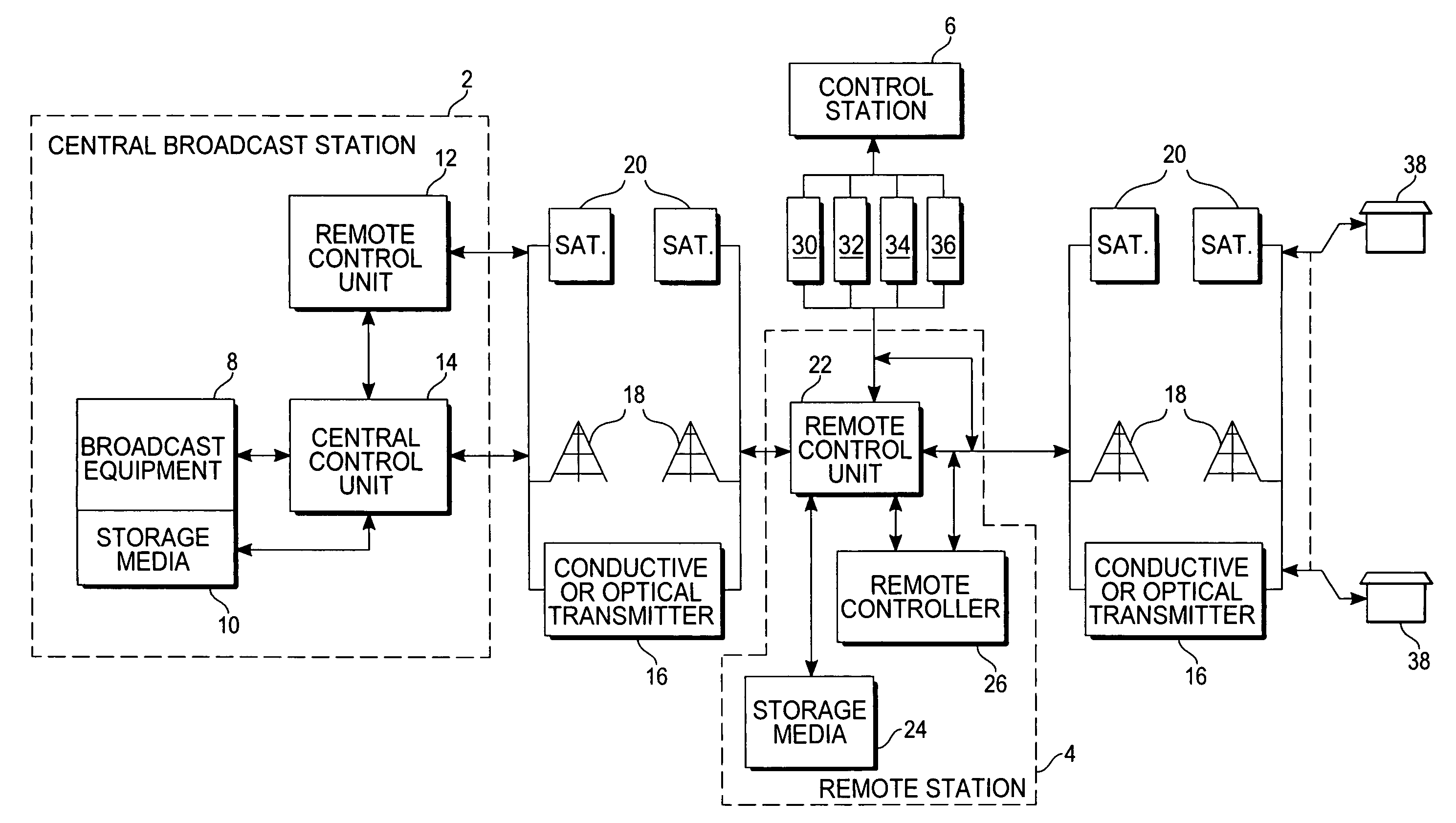
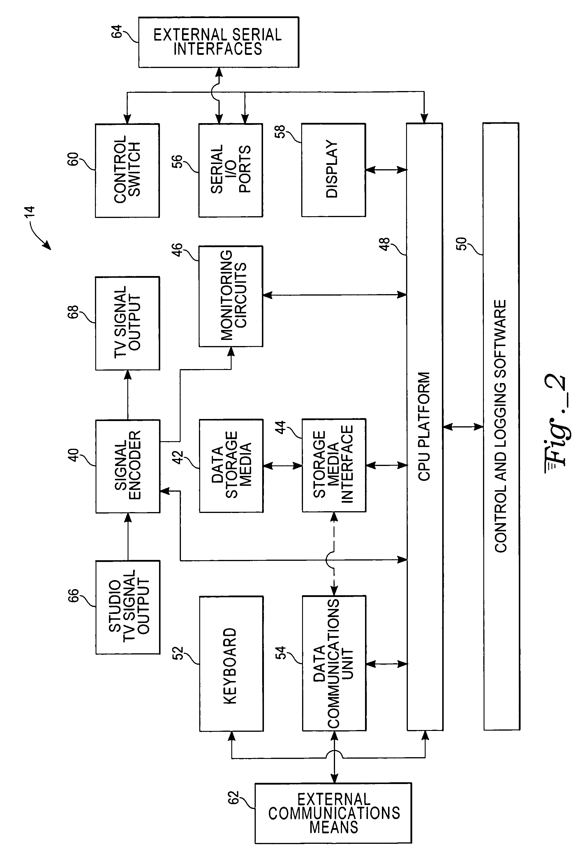
[0017]In one embodiment of the invention, additional material (for example, commercials or any kind of programming) can be inserted into a media signal when the signal is being broadcast from a central source and received by a remote receiver adapted for rebroadcasting the media signal to a number of end user units. The system comprises a central insertion control unit and a remote insertion control unit. The central insertion control unit, as its name implies, centrally controls the insertion of the additional material. The central control unit connects to the broadcast equipment of the central source, and incorporates a control signal and an information signal into the television signal. The central control unit comprises storage media, a processor, an encoder, a data communications unit and a serial interface. The processor controls and monitors the insertion of the additional material, and is connected to the storage media, the encoder, and the data communications unit. The storage media stores control information as well as the additional material information and logging information. The encoder encodes the control and information signals into the broadcast television signal. The data communications unit and the serial interface connect to external devices adding flexibility to the overall system.
[0024]In an alternate embodiment of the invention, a central insertion control apparatus is comprised of a processor, storage media, an encoder, a data communications unit and a serial interface. The processor controls and monitors the insertion of the additional material, and is connected to the storage media, the encoder, and the data communications unit. The storage media stores control information as well as the additional material information and logging information. The data communications unit and the serial interface connect to external devices adding flexibility to the overall system. The encoder encodes the control and information signals into the broadcast media signal. In one embodiment, the encoder is a Teletext encoder for encoding the control signal into a Teletext compatible format transparent to a standard Teletext receiver. The control signals comprise a cue signal for transferring information about play lists and an action signal for triggering an insertion of a predefined segment of additional material. Encoding the control signal in a Hamming coded format adds greater reliability to the system. In an alternate aspect of the invention, the control signals contain a clock run in specification, a framing code, a data channel specification, a designation code, a security access code, a format signal, an action signal, a security code, a package identifier, and a magic number.

Problems solved by technology

The reasons for this exclusivity are due to the high production cost for commercials and, perhaps above all, the fact that a very large number of consumers view a broadcast, thus motivating a high price per broadcast commercial.
Advertising production costs decline from year-to-year.
Moreover, as rebroadcast systems, such as various radio and cable television channels, increase, the viewer groups fragment and segment themselves.
Analog and partly mechanical systems present problems concerning the reliability of an advertisement segment segueing into the main television signal.
However, this system fails to solve the problem of reliably synchronizing and cueing additional signals into a broadcasting or other communication channel, and reliability in remote control of insertion apparatus.
In particular, it is a problem to achieve a technical implementation that satisfies reliability requirements to a cost that is reasonable to a larger group of advertisement buyers.
By their very nature, these cueing systems lack accuracy, flexibility, reliability and security.
These cueing systems are not frame accurate which limits their use.
The “stop” and “go” nature of their cue results in a 5–8 second delay.
This delay has to be adjusted at the remote or headend site for each television network, resulting in burdensome overhead.
Moreover, standard solutions are schedule dependent, and thus less flexible.
Consequently, such a system lacks flexibility, accuracy, and security.
The broadcaster would need to update the commercial media shown during a news story, because it may not be appropriate to show child-oriented commercials during a news report.
These updates required by cue-tone systems require high overhead in terms of communication time and human intervention.
Conventional systems are unreliable.
The setting of these windows is often haphazard and requires additional human intervention to do the manual entry.
The use of time windows is especially burdensome when a schedule changes quickly.
Another problem with standard cue-tone and general-purpose interface based systems are that they offer no inherent security for media channels or cable networks that deploy them.
Video pirates can easily insert unauthorized materials during a commercial break.
This is especially a problem for global satellite and cable channels that cannot, by their very nature, control and man remote sites in every country.

Method used


Image

  • Apparatus and method for insertion of material in broadcasting
  • Apparatus and method for insertion of material in broadcasting
  • Apparatus and method for insertion of material in broadcasting

Examples


Embodiment Construction

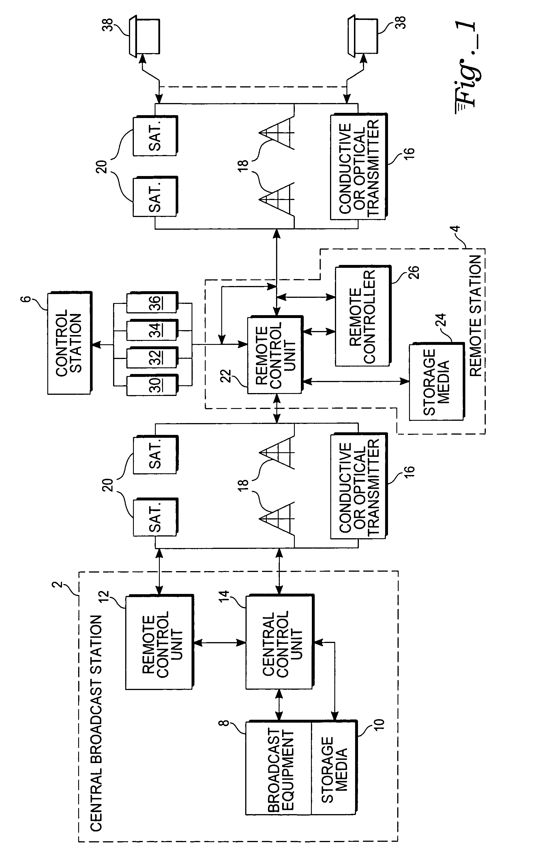
[0046]The present invention will now be disclosed with reference to a functional block diagram of an exemplary broadcast system of FIG. 1. It is well understood that such a system of the present design may apply to any audio, video or multimedia broadcast system as is known in the art. Such systems include, but are not limited to, conventional television, digital television, high-definition television (“HDTV”), radio, digital audio radio, or any similar multimedia broadcast system. The invention may also be extended to any compressed or encrypted multimedia broadcast systems without inventive faculty. For illustrative purposes only, an standard television embodiment is described in the detailed description. The example used is only provided to enable any person skilled in the art to make or use the present invention. Thus, the present invention is not intended to be limited to the embodiments shown herein, but is to be accorded the widest scope consistent with the claims herein.

[004...


PUM


Abstract

A system, apparatus, and method for local insertion of analog or digital material into a television broadcast signal. A central insertion control unit controls the insertion of additional material while a remote insertion control unit locally controls the insertion of the additional material. The central insertion control unit contains a processor, storage media, and an encoder for encoding control and information signals into a broadcast signal. The control signal contains a cue signal for information about play lists, and an action signal for triggering insertion of the additional material. The control signal is encoded into a line of the vertical blanking interval. Once the control is detected by the remote insertion control unit the additional material is played and broadcast.

Description

[0001]This is a continuation-in-part of application Ser. No. 08 / 809,872, filed Jul. 14, 1997, now abandoned, which is a 371 of application Ser. No. PCT / SE95 / 01056, filed Sep. 18, 1995.BACKGROUND OF THE INVENTION[0002]I. Field of the Invention[0003]The present invention relates to an apparatus and method for local inserting analog or digital material, such as an audio-video advertisement, into analog or digital broadcast signal. More specifically, the present invention relates to a novel method and system for inserting additional material into a multimedia or television (“TV”) channel signal being broadcast from a central source and received by a remote receiver adapted for rebroadcasting the television signal to a number of end viewer units. This application claims the benefit of priority to Swedish Application No. 94 03109-3, filed Sep. 16, 1994, and is a continuation-in-part of U.S. patent application Ser. No. 08 / 809,872, entitled “Apparatus and Method for Local Insertion of Mater...

Claims


Application Information

Patent Timeline
IPC IPC(8): H04N7/10H04N7/088
CPCH04H20/103H04N7/10H04N7/0882H04N7/088
Inventor RIDDERHEIM, STEFANHEERAH, ATMA
Owner PINNACLE SYST INC A CORP CALIFORNIA
Learn More