
Fast high-accuracy multi-dimensional pattern inspection

a multi-dimensional, fast technology, applied in the field of machine vision, can solve the problems of inability to detect fine variations, inability to reliably classify pixels as objects or background, and severe degradation of accuracy

Inactive Publication Date: 2006-01-10
COGNEX CORP
View PDF20 Cites 12 Cited by
  • Summary
  • Abstract
  • Description
  • Claims
  • Application Information

AI Technical Summary

Benefits of technology

The invention is a method and system for identifying differences between a stored pattern and an object image. The system extracts pattern features from the pattern and compares them to image features from the object image. The process of identifying differences is called inspection. The invention is faster and more accurate than previous methods and can be used in conjunction with coarse-fine methods for pattern inspection. The system uses a stored pattern that represents an ideal example of the object to be found and inspected. The pattern can be created from a training image or synthesized from a geometric description.

Problems solved by technology

One limitation is that accuracy can be severely degraded if some of the object is missing or occluded, or if unexpected extra features are present.
Another limitation is that the values available for inspection purposes represent coarse features of the object, and cannot be used to detect fine variations.
The most severe limitation, however, is that except under limited and well-controlled conditions there is in general no reliable method for classifying pixels as object or background.
These limitations forced developers to seek other methods for pattern location and inspection.
One limitation, however, is that a binarization threshold is needed, which can be difficult to choose reliably in practice, particularly under conditions of poor signal-to-noise ratio or when illumination intensity or object contrast is subject to variation.
Accuracy is typically limited to about one whole pixel due to the substantial loss of information associated with thresholding.
Even more serious, however, is that binary template matching cannot measure object orientation and size.
Furthermore, accuracy degrades rapidly with small variations in orientation and / or size, and if larger variations are expected the method cannot be used at all.
The situation regarding orientation and size, however, is not much improved with respect to binary template matching.
Another limitation is that in some applications, contrast can vary locally across an image of an object, resulting in poor correlation with the stored pattern, and consequent failure to correctly locate it.
Note that such methods would not work well with binary template matching, due the much more severe pixel quantization errors associated with binary images.
One problem with these methods is the severe computational cost, both of digital re-sampling and of searching a space with more than 2 dimensions.
The location accuracy of these methods is limited both by how finely the multidimensional space is searched, and by the ability of the discrete pixel grid to represent small changes in position, orientation, and scale.
The fineness of the search can be chosen to suit a given application, but computational cost grows so rapidly with resolution and number of dimensions that practical applications often cannot tolerate the cost or time needed to achieve high accuracy.
The limitations of the discrete pixel grid are more fundamental—no matter how finely the space is searched, for typical patterns one cannot expect position accuracy to be much better than about ¼ pixel, orientation better than a degree or so, and scale better than a percent or so.
Some differences, however, will result from the re-sampling process itself, because again the pixel grid cannot accurately represent small variations in orientation and scale.
These differences are particularly severe in regions where image gray levels are changing rapidly, such as along object boundaries.
Since in general, differences due to re-sampling cannot be distinguished from those due co object defects, inspection performance is compromised.

Method used


Image

  • Fast high-accuracy multi-dimensional pattern inspection
  • Fast high-accuracy multi-dimensional pattern inspection
  • Fast high-accuracy multi-dimensional pattern inspection

Examples


Embodiment Construction

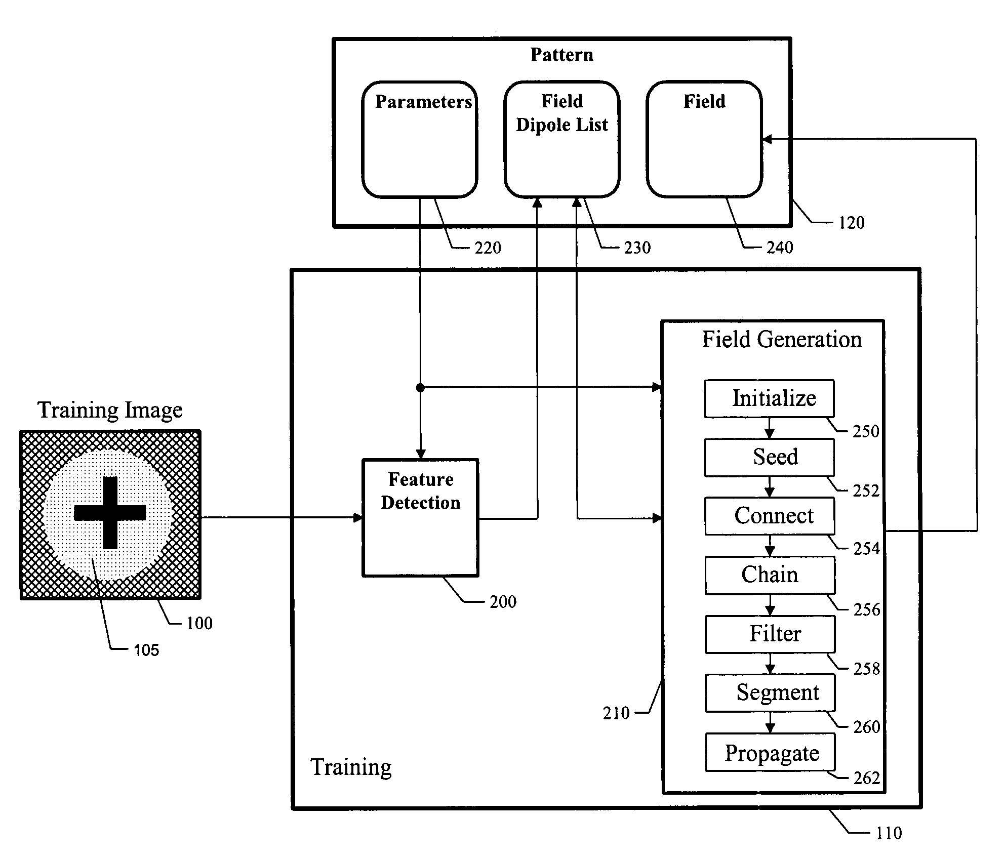
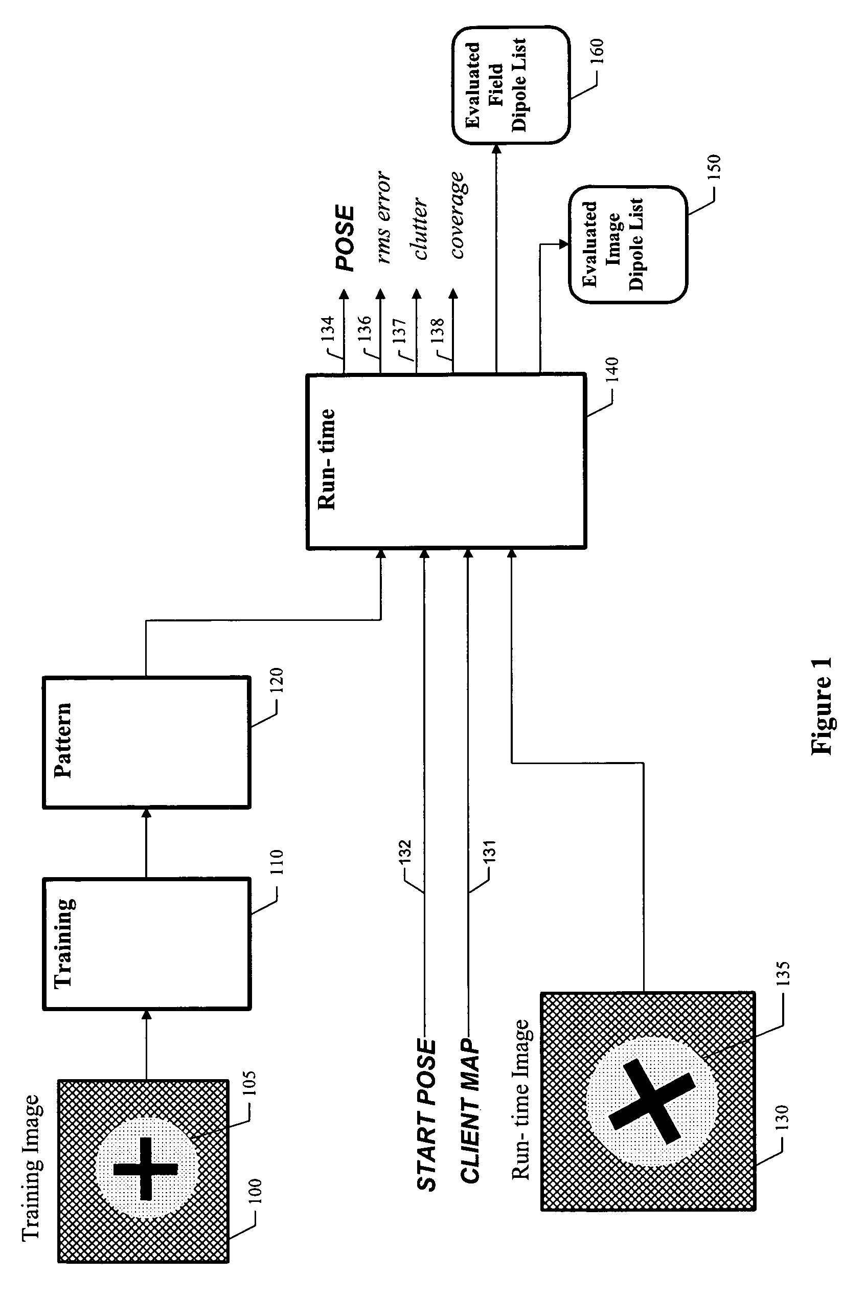
[0085]In the following figures, “modules” can be implemented as software, firmware, or hardware. Moreover, each module may include sub-modules, or “steps”, each of which can be implemented as either hardware, software, or some combination thereof. FIG. 1 is a high-level block diagram of one embodiment of the invention. A training (model) image 100 containing an example of a pattern 105 to be used for localization and / or inspection is presented. A training module 110 analyzes the training image and produces a stored model pattern 120 for subsequent use. At least one run-time image 130 is presented, each such image containing zero or more instances of patterns 135 similar in shape, but possibly different in size and orientation, to the training (model) pattern 105.

[0086]Each run-time image 130 has an associated client map 131, chosen by a user for a particular application. A client map is a coordinate transformation that maps, i.e., associates points in an orthonormal but otherwise ar...


PUM


Abstract

A method and apparatus are provided for identifying differences between a stored pattern and a matching image subset, where variations in pattern position, orientation, and size do not give rise to false differences. The invention is also a system for analyzing an object image with respect to a model pattern so as to detect flaws in the object image. The system includes extracting pattern features from the model pattern; generating a vector-valued function using the pattern features to provide a pattern field; extracting image features from the object image; evaluating each image feature, using the pattern field and an n-dimensional transformation that associates image features with pattern features, so as to determine at least one associated feature characteristic; and using at least one feature characteristic to identify at least one flaw in the object image. The invention can find at least two distinct kinds of flaws: missing features, and extra features. The invention provides pattern inspection that is faster and more accurate than any known prior art method by using a stored pattern that represents an ideal example of the object to be found and inspected, and that can be translated, rotated, and scaled to arbitrary precision much faster than digital image re-sampling, and without pixel grid quantization errors. Furthermore, since the invention does not use digital image re-sampling, there are no pixel quantization errors to cause false differences between the pattern and image that can limit inspection performance.

Description

[0001]This is a continuation of U.S. patent application Ser. No. 09 / 746,147 filed Dec. 22, 2000 which is now U.S. Pat. No. 6,658,145 issued on Dec. 2, 2003, which is a continuation of U.S. patent application Ser. No. 09 / 001,869, filed Dec. 31, 1997 (now abandoned), which is a continuation-in-part to U.S. patent application Ser. No. 08 / 979,588, filed Nov. 26, 1997, now abandoned.FIELD OF THE INVENTION[0002]This invention relates to machine vision, and particularly to systems for pattern inspection in an image.BACKGROUND OF THE INVENTION[0003]Digital images are formed by many devices and used for many practical purposes. Devices include TV cameras operating on visible or infrared light, line-scan sensors, flying spot scanners, electron microscopes, X-ray devices including CT scanners, magnetic resonance imagers, and other devices known to those skilled in the art. Practical applications are found in industrial automation, medical diagnosis, satellite imaging for a variety of military,...

Claims


Application Information

Patent Timeline
Patent Type & Authority Patents(United States)
IPC IPC(8): G06K9/46G06K9/66G06T7/00G06V10/24
CPCG06K9/32G06T7/0046G06K9/6203G06T7/75G06V10/24G06V10/7515
Inventor SILVER, WILLIAMWALLACK, AARONWAGMAN, ADAM
Owner COGNEX CORP
Learn More