
Load detecting system and automatic washing machine equipped with a system for detecting the magnitude of the load acting on a magnetostrictive element

a technology of magnetostrictive elements and load detecting systems, which is applied in the direction of other washing machines, force measurement, instruments, etc., can solve the problems of inability to obtain sufficient high accuracy of detection, and the hysteresis of the load sensor is great, so as to accurately control the laundering operation, accurately detect the load acting, and reduce the influence of the element hysteresis

Inactive Publication Date: 2006-01-10
QINGDAO HAIER WASHING MASCH CO LTD +1
View PDF9 Cites 30 Cited by
  • Summary
  • Abstract
  • Description
  • Claims
  • Application Information

AI Technical Summary

Benefits of technology

[0015]Since the detection preparing current has a current value greater than the maximum value of the detecting current, the passage of the detection preparing current deforms the magnetostrictive element in such a direction as to offset the strain thereof caused by the action of the load. The detecting current is thereafter passed through the coil, whereby the magnetostrictive element resumes strain corresponding to the load acting thereon. Thus, every time the load is to be detected, the element is deformed once in such a direction as to nullify the load, thereafter deformed in the same direction and eventually given an amount of deformation corresponding to the magnitude of the load. This eliminates the likelihood that every load detected will involve a variation due to the influence of residual magnetism attributable to hysteresis, consequently ensuring high accuracy of detection.
[0020]Further stated specifically, the control means passes the detection preparing current through the coil, then interrupts the passage of the current for a specified period of time and thereafter passes the detecting current through the coil. This makes abrupt contraction or expansion of the element moderate to suppress noise of collision to be produced upon the magnetostrictive element colliding with a member positioned around the element. Further when the detection preparing current is changed over to the detecting current by the control means with a specified time constant, the occurrence of the noise of collision can be suppressed effectively.
[0022]The present invention provides an automatic washing machine which has the load detecting system of the invention described as disposed in a position for receiving the load of laundry and washing water. The load of the laundry weighing hundreds of grams to several kilograms and washing water weighing tens of kilograms can be detected accurately by the detecting system to control the laundering operation in response to the resulting detection signal.
[0023]The load detecting system of the present invention is adapted to accurately detect the load acting on the magnetostrictive element with the influence of hysteresis of the element diminished, and the automatic washing machine equipped with such an accurate load detecting system is adapted for an accurately controlled laundering operation.

Problems solved by technology

Although adapted to realize high sensitivity, such a load sensor has the problem of being great in hysteresis because the magnetostrictive element itself has great energy of crystal magnetic anisotropy to thereby impair the accuracy of detection.
Accordingly, the sensor must have a broad load detecting range, whereas the sensor has the problem that the influence of hysteresis markedly appears in the range of small loads to be measured, consequently making it impossible to obtain sufficiently high accuracy of detection.

Method used


Image

  • Load detecting system and automatic washing machine equipped with a system for detecting the magnitude of the load acting on a magnetostrictive element
  • Load detecting system and automatic washing machine equipped with a system for detecting the magnitude of the load acting on a magnetostrictive element
  • Load detecting system and automatic washing machine equipped with a system for detecting the magnitude of the load acting on a magnetostrictive element

Examples


Embodiment Construction

[0035]With reference to the drawings, a detailed description will be given of an embodiment, i.e., an automatic washing machine equipped with a load detecting system of the invention.

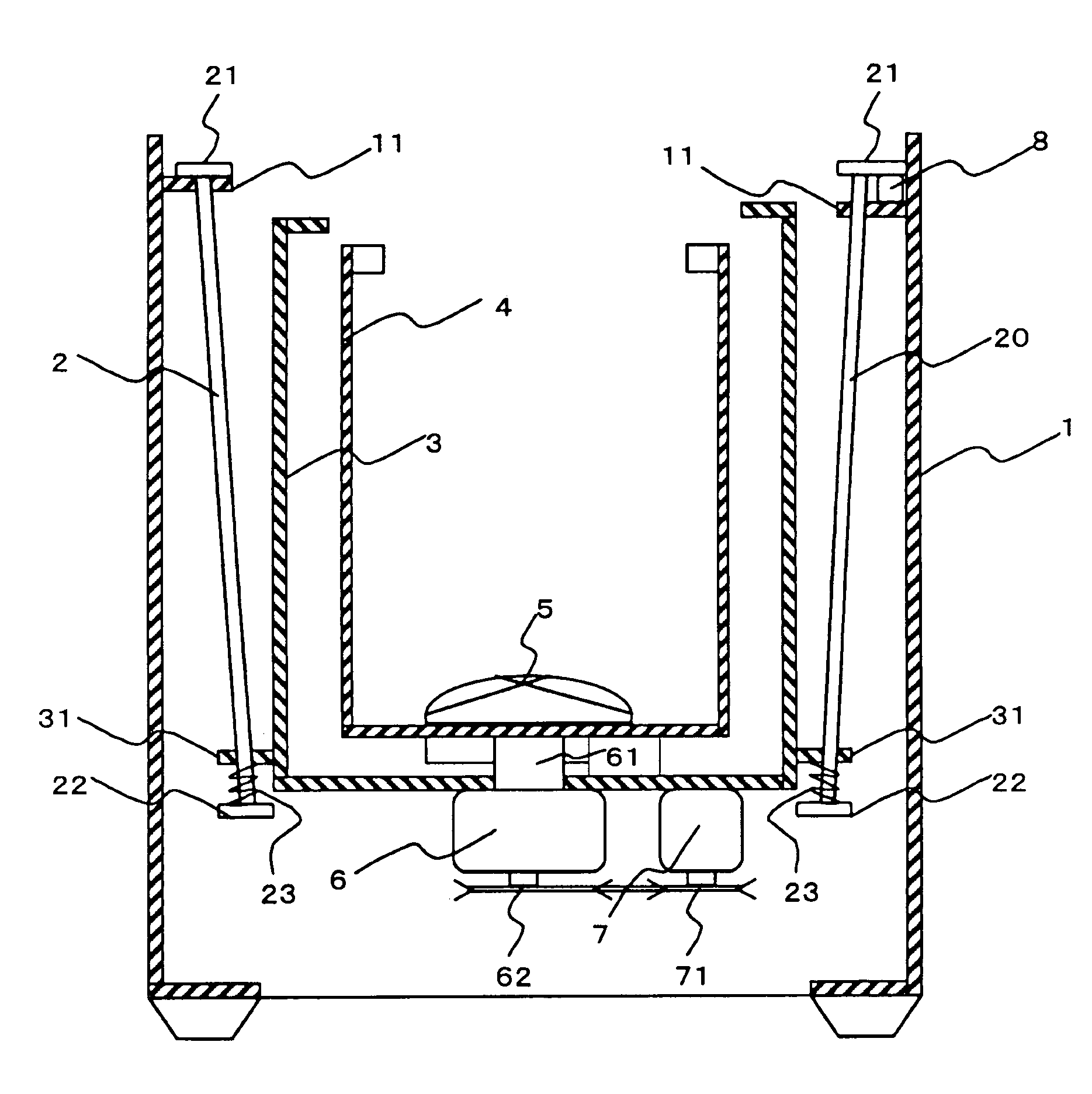
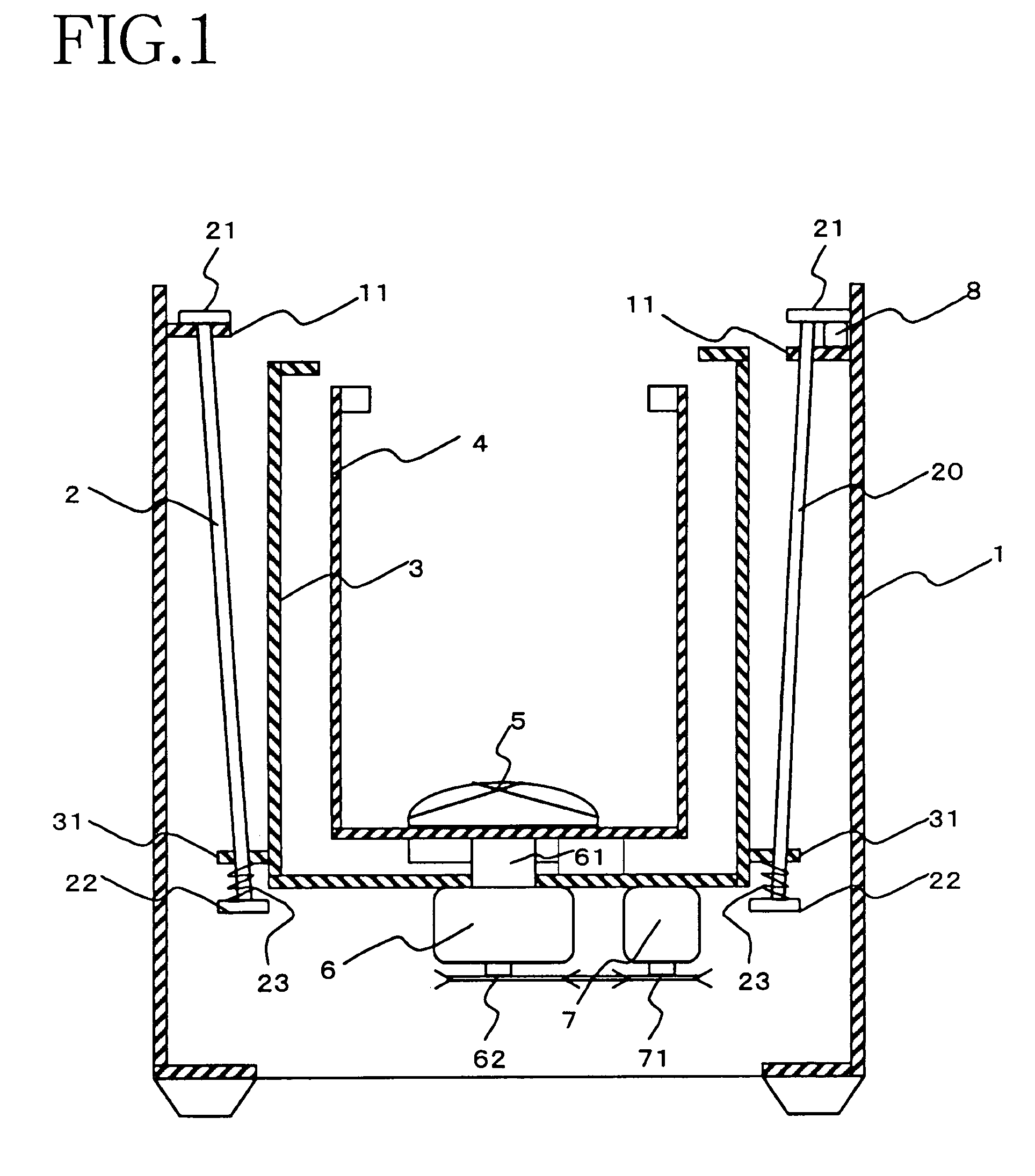
[0036]The automatic washing machine of the present embodiment has an outer tub 3 supported in suspension by four suspending rods 2, 20 inside a casing 1. Provided inside the outer tub 3 is an inner tub 4 for laundering and dewatering.

[0037]A casing bracket 11 is provided at each of four upper corners of the casing 1, and an outer tub bracket 31 is provided at each of four lower corners of the outer tub 3. Disposed at the upper end of each suspending rods 2 or 20 is an upper bracket 21 for holding the suspending rod 2 or 20 to the casing bracket 11. Provided at the lower end of the suspending rod 2 or 20 is a lower bracket 22 for holding the suspending rod 2 or 20 to the outer tub bracket 31.

[0038]Interposed between the upper surface of each lower bracket 22 for the suspending rod 2 or 20 and the lower s...


PUM


Abstract

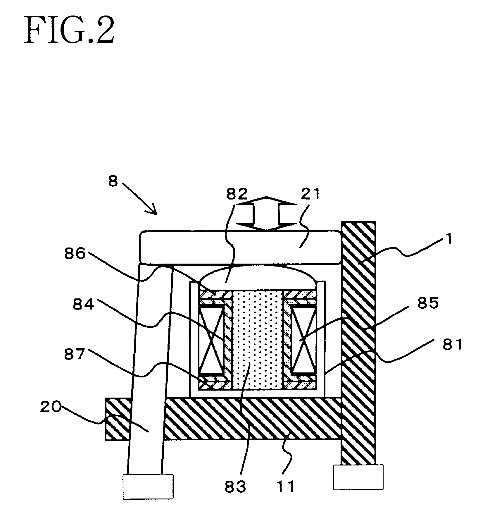
The invention provides a load detecting system comprising a core (83) of magnetostrictive material, a coil (85) disposed in the vicinity of the core, and a load detecting circuit (10) connected to the coil (85) for detecting the magnitude of a load acting on the core (83). The load detecting circuit (10) comprises an exciting circuit (102) for passing an a.c. detecting current through the coil (85), a pulse current generating circuit (103) for passing through the coil a detection preparing current having a current value greater than the maximum value of the detecting current, a change-over circuit (104) for effecting a change-over between the exciting circuit (102) and the pulse current generating circuit (103) to pass the detecting current through the coil after passing the detection preparing current therethrough, and a microcomputer (100) for deriving the magnitude of the load acting on the magnetostrictive element based on an impedance variation produced in the coil during the period of passage of the detecting current through the coil.

Description

TECHNICAL FIELD[0001]The present invention relates to load detecting systems for detecting the magnitude of a load acting on a magnetostrictive element based on the variation of impedance of a coil, and to automatic washing machines adapted to control the laundering operation thereof by detecting the load of laundry and washing water by the load detecting system.BACKGROUND ART[0002]Magnetostrictive elements have such a property that the element has its magnetic permeability varied and is deformed by the variation of the magnetic permeability when subjected to a magnetic field by passing current through a coil disposed in the vicinity of the element. The magnetostrictive element is used as an actuator or oscillator since the amount of deformation and the stress produced due to the deformation are great.[0003]Conversely when the magnetostrictive element is deformed by applying an external force thereto, the element has its magnetic permeability altered by the deformation. For example,...

Claims


Application Information

Patent Timeline
IPC IPC(8): G01B7/16G01L1/00D06F37/24D06F39/00G01G19/52G01L1/12
CPCD06F37/24D06F39/003G01L1/127G01L1/125G01G19/52D06F34/18
Inventor KAKUTANI, KAZUSHIGEKISHIMOTO, KEIJIYOKOTANI, KAZUNOBUAOKI, HIDEAKIUSHIJIMA, KAZUFUMIFUKUNAGA, TAKESHINAKANISHI, MINORUKONDO, FUMITAKE
Owner QINGDAO HAIER WASHING MASCH CO LTD
Learn More