
Directly tuned filter and method of directly tuning a filter

a filter and filter technology, applied in the field of direct tuning of filters, can solve the problems of difficult or impossible to achieve using manual tuning methods, and low efficiency of automatic tuning methods, so as to achieve the effect of reducing the noise of master-slave circuits, avoiding the effect of affecting the performance of the master and slave circuits, and avoiding the effect of manual tuning

Active Publication Date: 2006-01-03
SMSC HLDG
View PDF20 Cites 30 Cited by
  • Summary
  • Abstract
  • Description
  • Claims
  • Application Information

AI Technical Summary

Benefits of technology

[0005]Methods of directly tuning an analog filter are provided. Advantageously, the characteristics of a filter to be adjusted can be determined by amplifying and shaping the input spectrum of the filter thereby eliminating the need for an input reference frequency signal.
[0006]The present invention preferably relies on sub-sampling of the filter output which allows the system to tune higher frequency signals using lower power sub-sampling ADCs. In some embodiments, applying the filter function directly to the input signal allows the input signal to be received continuously even while the filter is being tuned. This increases the data transfer rate of the filter and adds flexibility to the overall system implementation.

Problems solved by technology

This has been traditionally accomplished with relatively expensive off chip ceramic or Surface Acoustic Wave (SAW) filters.
This is difficult or impossible to achieve using manual tuning methods because manual tuning methods cannot adequately accommodate environmental variations such as temperature or power supply changes.
Master-Slave tuning suffers from component mismatch and disparate circuit noise in the master and slave circuits.

Method used


Image

  • Directly tuned filter and method of directly tuning a filter
  • Directly tuned filter and method of directly tuning a filter
  • Directly tuned filter and method of directly tuning a filter

Examples


Embodiment Construction

[0029]The present invention now will be described more fully with reference to the accompanying drawings, in which embodiments of the invention are shown. The invention may be embodied in many different forms and should not be construed as limited to the embodiments set forth herein; rather, these embodiments are provided so that this disclosure will be thorough and complete, and will fully convey the scope of the invention to those skilled in the art. In the drawings, like numbers refer to like elements throughout.

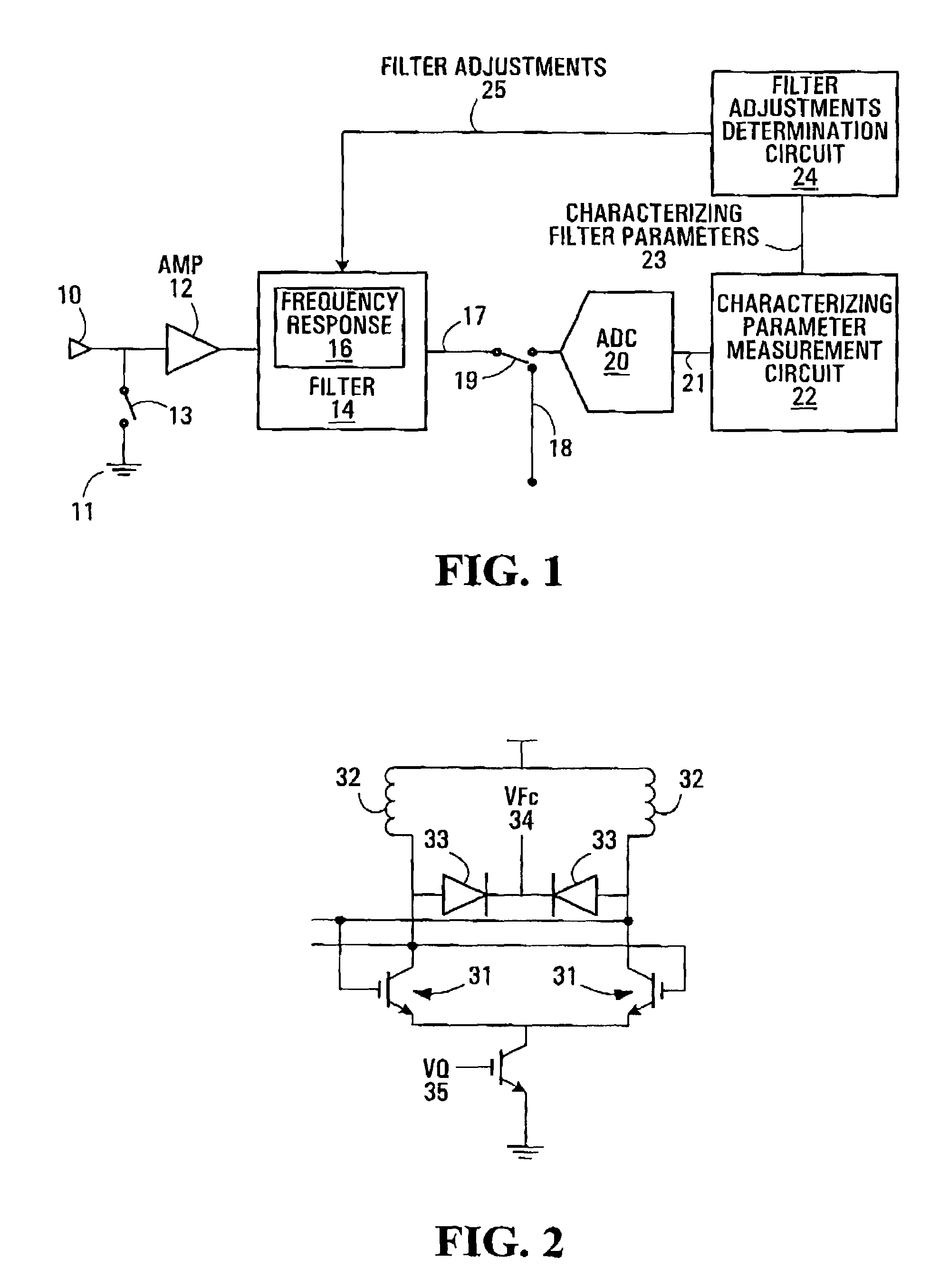
[0030]Referring now to FIG. 1, a first example of a digitally tuned filter arrangement is shown. An input signal 10 is shown input to an amplifier 12 which is connected to an analog filter 14. The input to the amplifier (AMP) 12 can alternatively be connected to ground 11 under control of switch 13. The filter 14 has an output 17 which is connectable either to an analog-to-digital converter (ADC) 20 or to an output 18 of the arrangement under the control of a switch 19. A...


PUM


Abstract

A Method for filter tuning using direct digital sub-sampling is provided. The tuning is accomplished in the digital domain by determining the filter characteristics from the shape of the transfer function. The input signal (1) is passed through the filter (3) and is then sub-sampled by and Analog-to-digital Converter (ADC) (5). The sub-sampled signal (6) is then processed in the digital domain using a digital circuit (7) that is used to determine the center frequency (Fc) and Quality factor (Q) and / or other important filter parameters. The Fc, Q and / or other important filter parameters are then adjusted by generating digital control signals (8) that can be converted to analog signals (10) using Digital-to-analog Converters (DACs) (9).

Description

FIELD OF THE INVENTION[0001]The invention relates to the tuning of filters such as integrated circuit (IC) filters. In particular, it relates to tuning of high frequency, high Q continuous time analog filters.BACKGROUND OF THE INVENTION[0002]Recent research on radio frequency integrated circuits (RFICs) has focused on the development of fully integrated radio receivers. There is an ongoing search for architectures that can deliver high selectivity and sensitivity, all at low cost and power consumption. It is well understood that the super-heterodyne architecture, with a high IF frequency, although difficult to integrate, has major advantages in terms of image rejection and selectivity. A major design hurdle for integrating the super-heterodyne receiver is on chip filtering. The architecture typically requires one or more high Q filters to provide good selectivity. This has been traditionally accomplished with relatively expensive off chip ceramic or Surface Acoustic Wave (SAW) filte...

Claims


Application Information

Patent Timeline
Patent Type & Authority Patents(United States)
IPC IPC(8): H04B1/10H03H11/12H03H21/00
CPCH03H21/0001H03H11/1291
Inventor MASON, RALPHDEVRIES, CHRIS
Owner SMSC HLDG
Learn More