
Erect image resin lens array and the manufacture thereof

a technology of resin lens array and erect image, which is applied in the field of erect image resin lens array, can solve the problems of uneven arrangement of lenslets, uneven image formation, and disturbance of the regular arrangement of rod lenslets, and achieve the effect of eliminating stray ligh

Inactive Publication Date: 2006-01-03
NIPPON SHEET GLASS CO LTD
View PDF4 Cites 22 Cited by
  • Summary
  • Abstract
  • Description
  • Claims
  • Application Information

AI Technical Summary

Benefits of technology

The present invention provides an erect image resin lens array that can effectively eliminate stray light, which is suitable for optical writing or reading. A resin lens plate is used to fabricate the array, which has regular patterns of convex lenslets arranged on its surface. The lenslets are arranged in a way that their centers are in parallel with the lengthwise side of the plate, and there are lines and grooves on the plate where a light absorbing film can be placed. The array can be stacked to increase its size, and it can be placed in a thin slit for image transmission. The invention also provides methods for manufacturing the resin lens plate and the array.

Problems solved by technology

Thus, regular arrangement of the rod lenslets is often disturbed, that is, an uneven arrangement of the lenslets may occur.
Such an uneven arrangement of the lenslets would affect the resolving power of the lens array and, if such a lens array is incorporated in a high-resolution image forming system (having, for example, a resolution as high as 1200 dpi) as is available on the recent market, will cause the formation of an uneven image.
However, because stray light includes a component passing through the lens body itself, shielding all the other parts than the lens body of each lenslet is not yet sufficient for completely eliminating the stray light component out of the light incident to the lenslet.
However, addition of such a structural element as septa to the lens array will increase the overall volume of the array itself, which will be undesirable in many applications.

Method used


Image

  • Erect image resin lens array and the manufacture thereof
  • Erect image resin lens array and the manufacture thereof
  • Erect image resin lens array and the manufacture thereof

Examples


Embodiment Construction

[0072]The preferred embodiments of the present invention will be described below with reference to the drawings.

[0073]The erect image resin lens array of the present invention is obtained by intimately stacking, via bonding, two or more resin lens plates each carrying a matrix of multiple convex lenslets on one or both of its surfaces. Such an erect image resin lens array obtained according to this invention must contain at least three lenslet carrying layers.

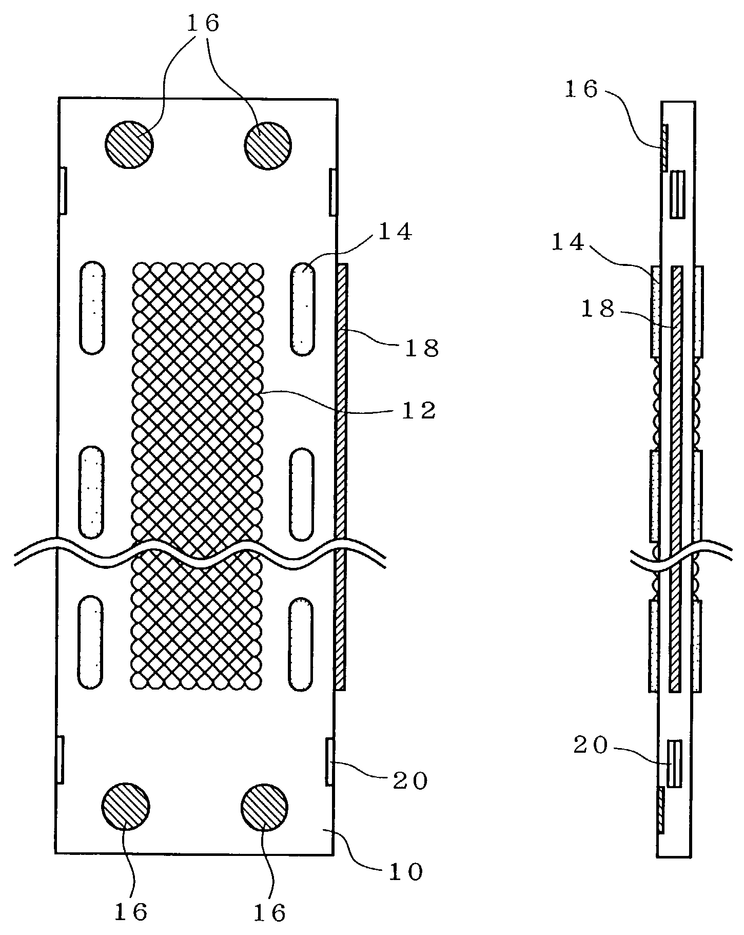
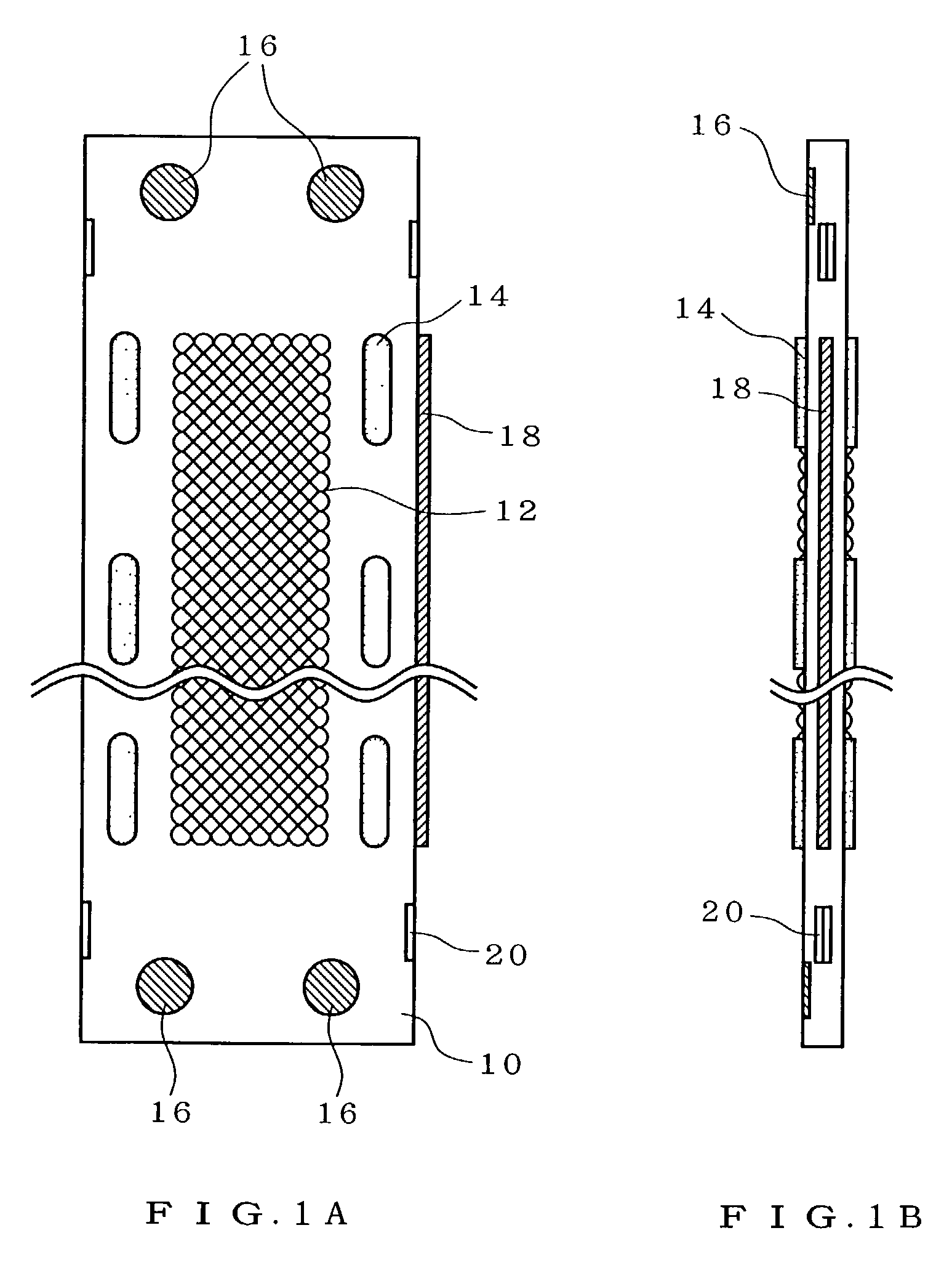
[0074]FIG. 1A is a plan view of a resin lens plate constituting an erect image resin lens array of this invention; and FIG. 1B is a lateral view of the same resin lens plate. The resin lens plate is prepared by injection molding. The material for the resin lens plate includes any known materials available to injection molding, but what is particularly preferred includes olefin resins, cyclo-olefin resins, and norbornene resins. What is commercially available includes ZEONEX (™) and ZEONOA (™) provided by Japan Zeon Co., and ART...


PUM

PropertyMeasurementUnit
depthaaaaaaaaaa
depthaaaaaaaaaa
depthaaaaaaaaaa

Abstract

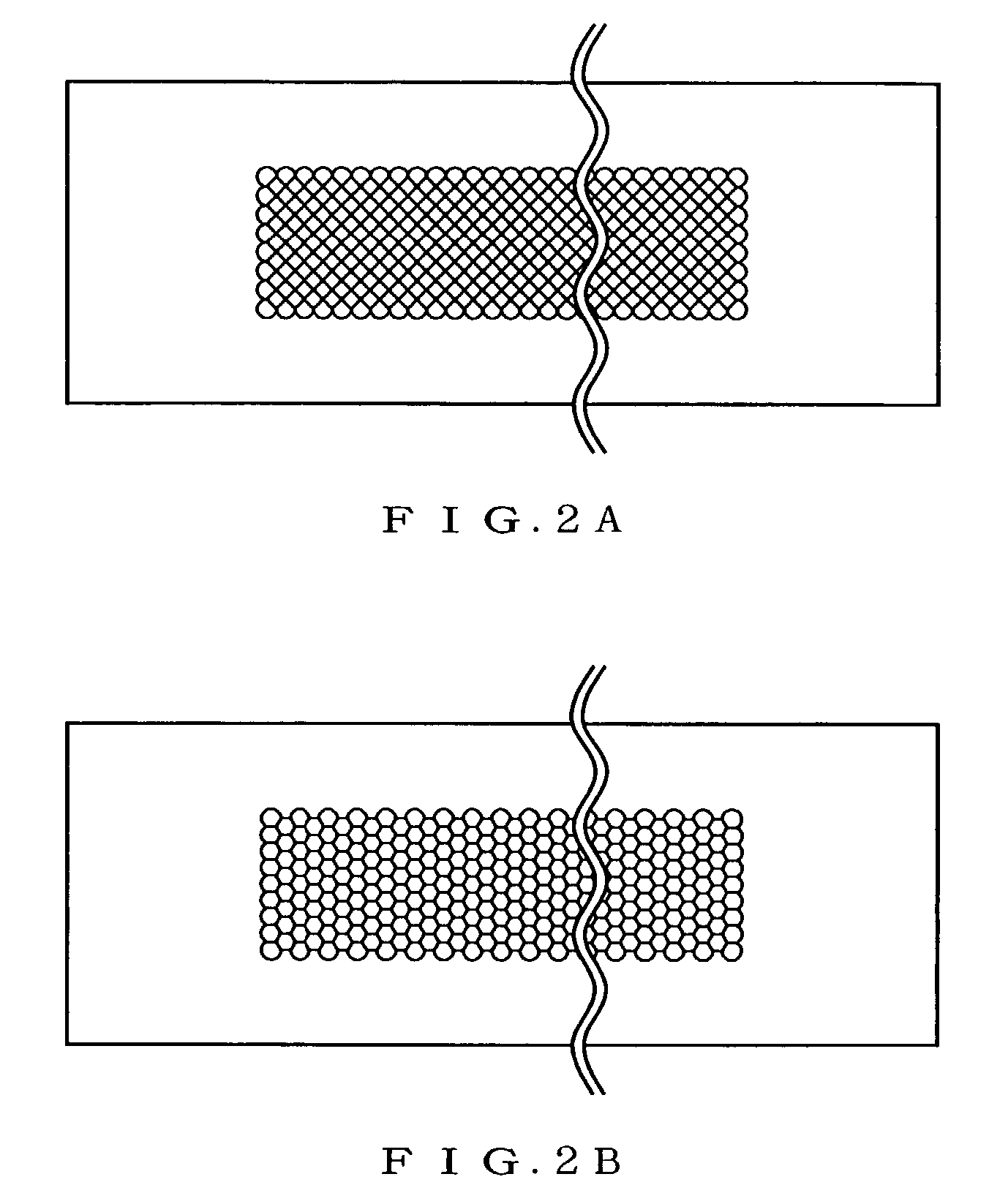
A resin lens plate has, on its planar surface, convex lenslets arranged in a regular pattern with adjacent lenslets being apart from each other by a specified center-to-center pitch. Each of the convex lenslets has a rectangular or hexagonal contour in a plan view of the plate, and the lenslets are arranged such that the direction in which the center-to-center distance between adjacent lenslets takes a maximum value is in parallel with the lengthwise side of the plate. A groove or a ridge is formed along the bisector of a center-to-center line drawn between each pair of adjacent lenslets, and a light absorbing film is formed over the groove or the ridge. The groove or ridge inhibits the entry of stray light to the lenslet from adjacent lenslets.

Description

FIELD OF THE INVENTION[0001]The present invention relates to an erect image resin lens array, particularly to an erect image resin lens array obtained by arranging convex lenslets each having a spherical or aspherical end surface in a regular pattern on a planar plate with adjacent lenslets being apart from each other by a specified pitch to produce a resin lens plate, and by stacking at least two such resin lens plates such that their lenslet carrying surfaces face each other. The present invention further relates to a method for manufacturing the erect image resin lens array.BACKGROUND OF THE INVENTION[0002]The conventional image forming optical system used as an image transmission unit for optical writing systems such as photo-printers, or for optical reading systems such as scanners often incorporates a rod lens array comprising rod lenslets each having a different refractive index. The erect image optical system incorporating such a lens array can be very compact in size. Howev...

Claims


Application Information

Patent Timeline
Patent Type & Authority Patents(United States)
IPC IPC(8): G02B27/10G02B3/00G03B21/62
CPCG02B3/0031G02B3/0056G03B21/625G02B3/0068G02B3/0075G02B3/0062B29C65/08B29C66/30223B29C66/54
Inventor NEMOTO, HIROYUKI
Owner NIPPON SHEET GLASS CO LTD
Learn More