
Plug inner frame with twisted blades

a technology of inner frame and twisted blade, which is applied in the direction of coupling contact members, coupling device connections, securing/insulating coupling contact members, etc., can solve the problems of electric shock, insulating layer is apt to be disengaged from the smooth metal surface of the blade, and insulating layer is easy to slide off, so as to reduce the manufacture cost

Inactive Publication Date: 2006-01-03
GEM TERMINAL IND
View PDF7 Cites 51 Cited by
  • Summary
  • Abstract
  • Description
  • Claims
  • Application Information

AI Technical Summary

Benefits of technology

[0008]An object of the present invention is to provide a plug inner frame with twisted blades to reduce the manufacture cost.

Problems solved by technology

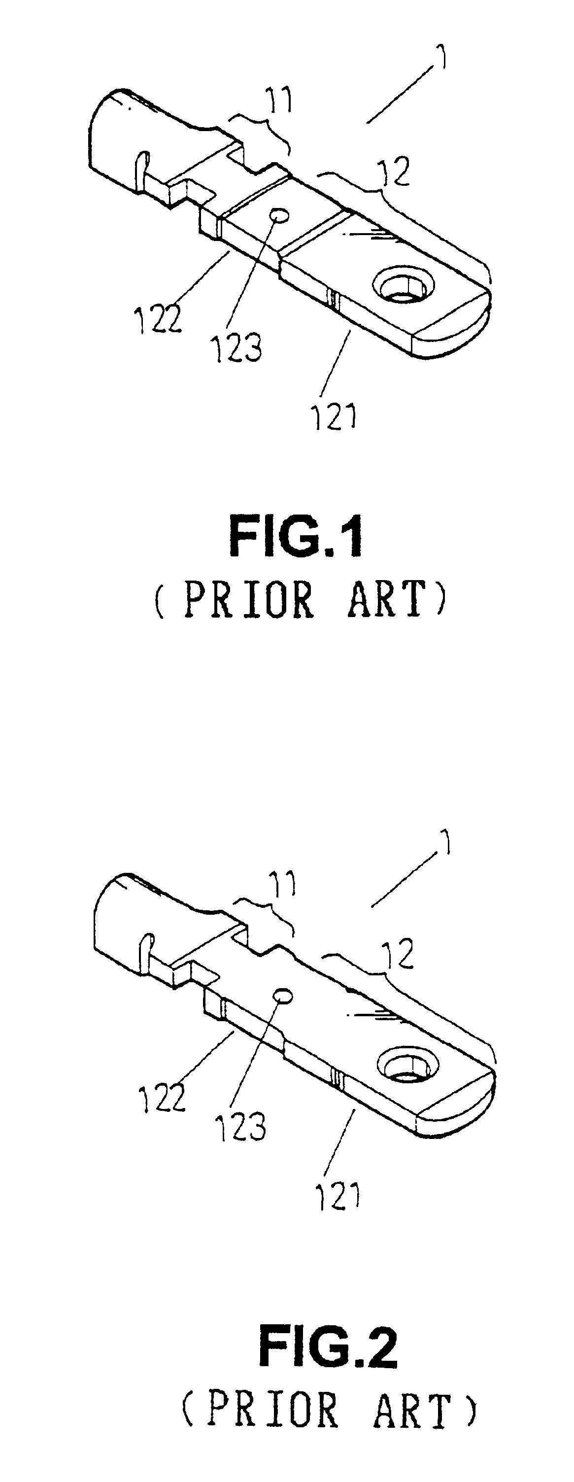
However, the insulating layer is apt to be disengaged from the smooth metal surface of the blade as a result of poor bonding force therebetween.
Thus, the insulating layer would slide easily, and sometimes may even fall.
The blade is then exposed again and thus could cause an electric shock.
The current wire-inserting machine could not proceed with the wire-inserting procedure on the plugs with twisted blades.
The manufacture cost is largely increased when seeking a solution to this end.
The appearance of the plug is thus adversely affected.

Method used


Image

  • Plug inner frame with twisted blades
  • Plug inner frame with twisted blades
  • Plug inner frame with twisted blades

Examples


Embodiment Construction

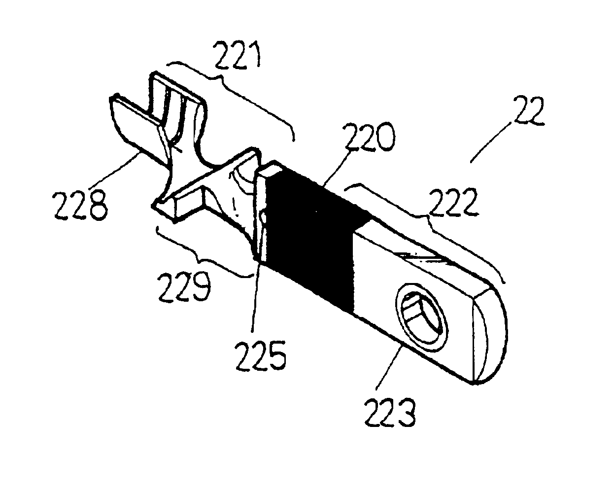
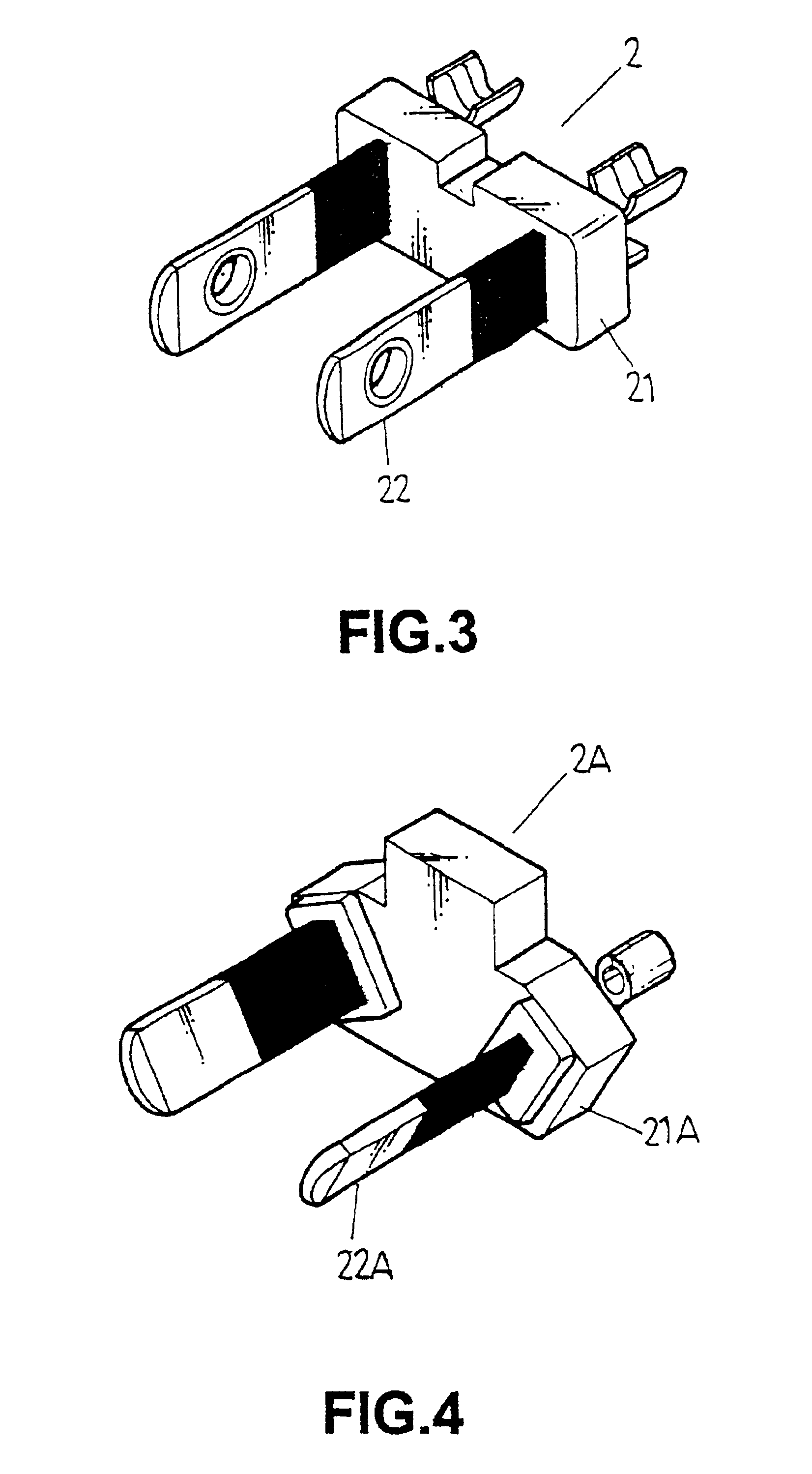
[0038]FIG. 7 illustrates a raw material of a plug blade 22 for manufacturing a plug inner frame (FIGS. 3 and 6) of a final plug in accordance with the present invention. The plug blade 22 includes an enclosed section 221 to be enclosed by a housing (not labeled, see FIGS. 3 and 6) and an exposed section 222. The exposed section 222 includes a wider front section 223 and a narrower rear section 224. A transverse through-hole 226 extends from a face of the narrower rear section 224 to the other face of the narrower rear section 224. A reinforcing guide slot 227 is defined in the narrower rear section 224 and communicated with the transverse through-hole 226. Also, the reinforcing guide slot 227 extends from a face of the narrower rear section 224 to the other face of the narrower rear section 224. The enclosed section 221 includes a shallow recess 225 in a front end thereof for filling plastic material into the narrower rear section 224. The faces of the narrower rear section 224 are ...


PUM


Abstract

A plug inner frame comprises a frame in the form of a block and at least two blades securely held by the frame. Each blade includes an enclosed section and an exposed section. Each blade includes an end having a wire-receiving groove. A neck is defined between the wire-receiving groove and the exposed section. The neck of each blade is so twisted that the wire-receiving grooves of the blades face the same direction.

Description

BACKGROUND OF THE INVENTION[0001]1. Field of the Invention[0002]The present invention relates to a plug inner frame with twisted blades to reduce the manufacture cost.[0003]2. Description of the Related Art[0004]A plug is a necessary element to all kinds of computers, electric appliances, etc and thus plays an important role in daily life. A typical plug generally comprises two or three blades or prongs manufacture, a wire is attached to an end of each blade, and the blades are then embedded into an inner frame. The semi-product comprised of the wires and the blades embedded in the inner frame is then placed into a mold for subsequent injection molding to form the final plug with a housing.[0005]Most advanced countries require each blade of the plug to be partially wrapped by an insulating layer at an exposed section thereof, thereby avoiding electric shocks in case that the plug is loosened. The insulating layer is generally made of plastic material and wraps a portion of the expos...

Claims


Application Information

Patent Timeline
IPC IPC(8): H01R13/04H01R4/18H01R13/41H01R13/504H01R43/24
CPCH01R13/652H01R43/24H01R24/30H01R2103/00
Inventor SU, TUN LI
Owner GEM TERMINAL IND
Learn More