
Portable light box

a light box and portability technology, applied in the field of portable light boxes, can solve the problems of not providing a carrying case, unable to provide a cover or other means for securing tools to prevent spillage and loss, and the laverick light box is not readily portable, so as to achieve convenient working surfaces

Inactive Publication Date: 2006-01-03
ARTOGRAPH
View PDF51 Cites 7 Cited by
  • Summary
  • Abstract
  • Description
  • Claims
  • Application Information

AI Technical Summary

Benefits of technology

"The present invention is a portable light box that includes a reflector assembly, carrying case, and divider. The reflector assembly has a base with an upper peripheral edge and a light source, such as an electric lamp, connected to an AC power source or a DC battery. The carrying case has a top and bottom portion and can hold the reflector assembly. The divider is removably received in the carrying case and separates tools from the reflector assembly to prevent damage. The invention allows for convenient and safe use of a portable light box for various applications."

Problems solved by technology

U.S. Pat. No. 4,654,762 issued to Laverick recognizes the advantages of incorporating a tool tray into the light box, but provides no cover or other means for securing the tools to prevent them from spilling and being lost when the light box is being moved from place to place.
As such, the Laverick light box is not readily portable since it must remain substantially horizontal and upright at all times to avoid spilling of the tools from the tool tray.
Furthermore, light boxes have heretofore failed to provide a carrying case so as to allow easy portability of the light box while at the same time protecting the work surface so as to avoid marring, soiling or otherwise damaging the work surface while the light box is being moved between work areas or is otherwise being transported or shipped or while in storage.

Method used


Image

  • Portable light box
  • Portable light box
  • Portable light box

Examples


Embodiment Construction

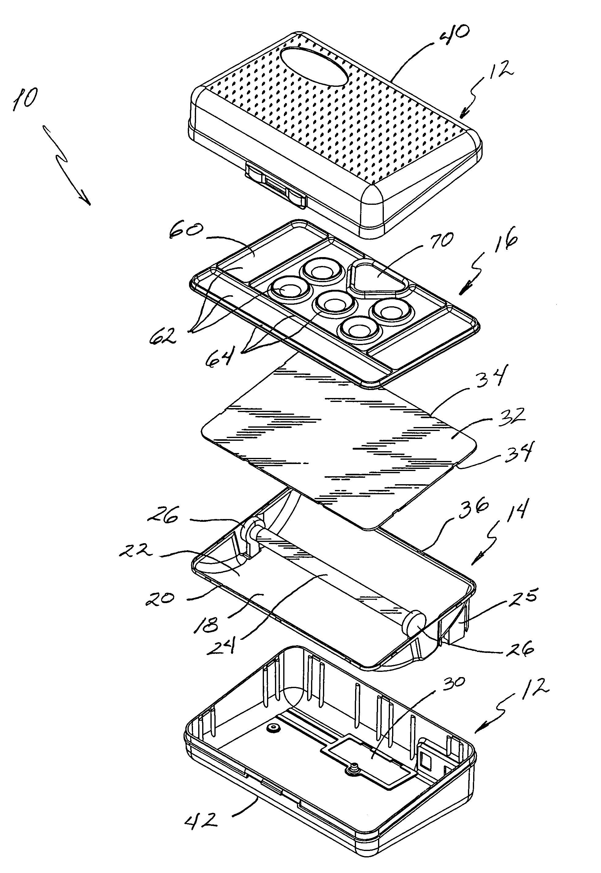
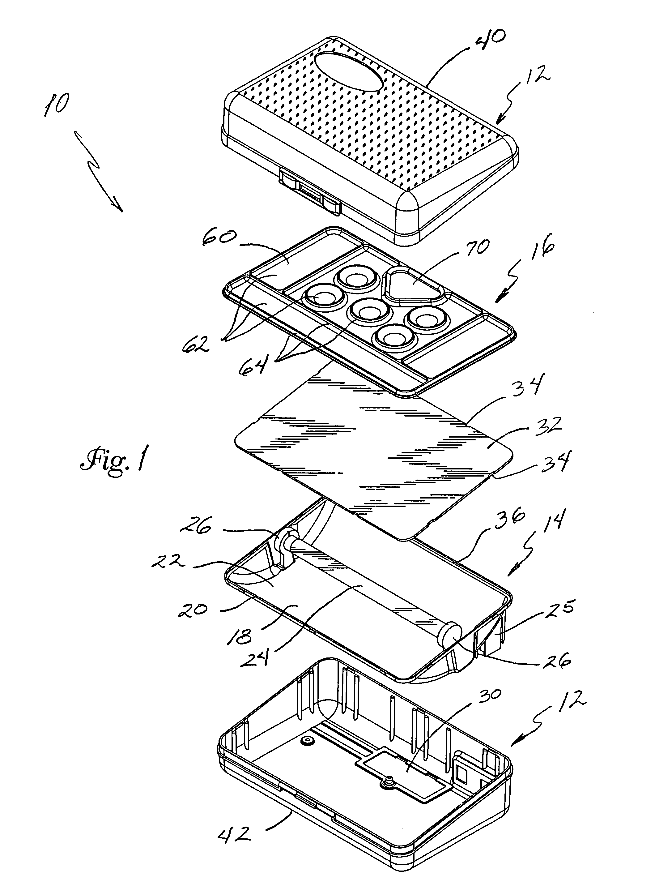
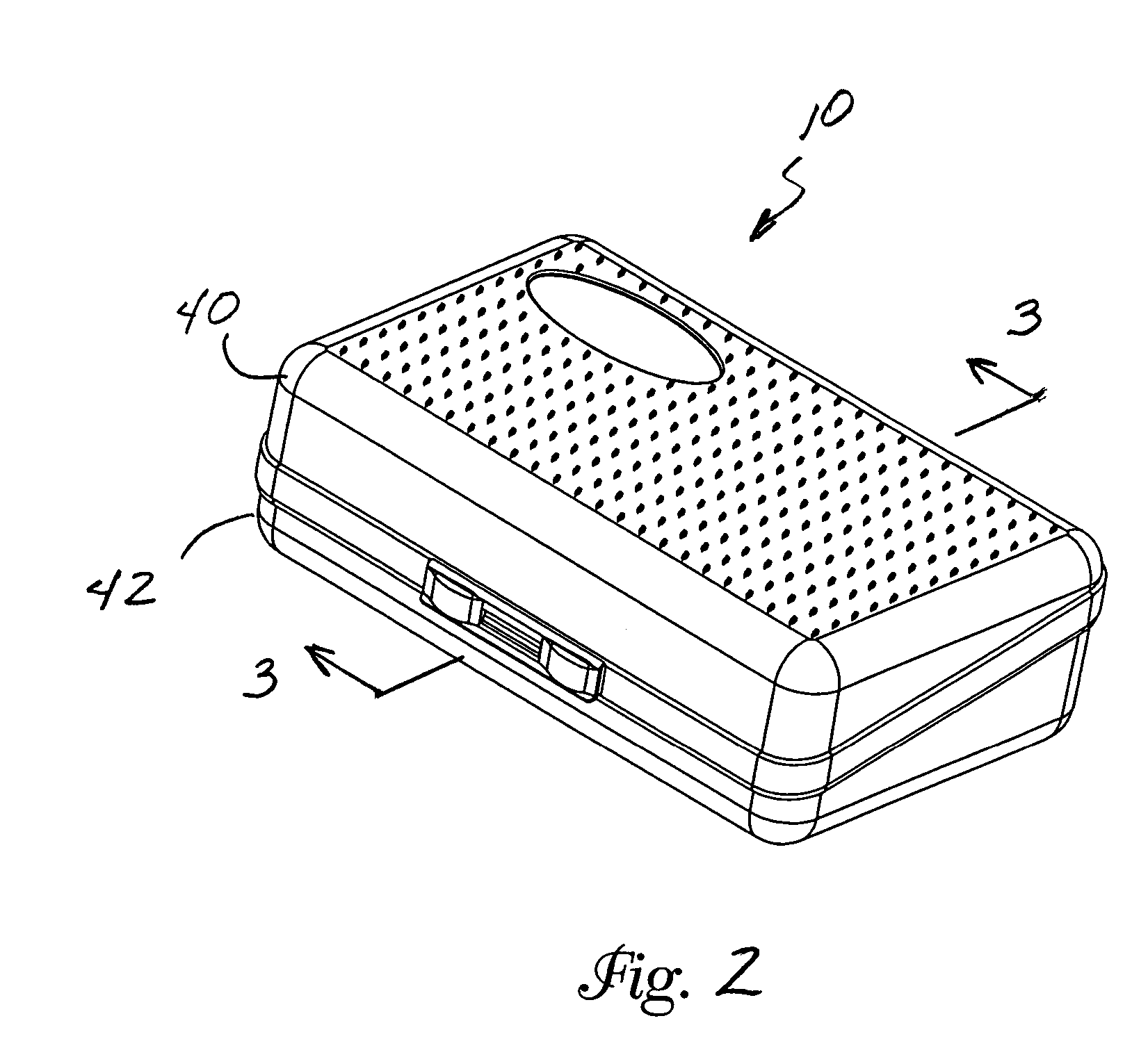
[0017]Drawing FIGS. 1–7 illustrate a preferred embodiment of the portable light box 10 of the present invention wherein like reference numerals designate corresponding parts throughout the several views of the drawings. An exploded perspective view of a preferred embodiment of the portable light box 10 of the present invention is illustrated in FIG. 1 showing the individual components comprising the preferred light box, including the preferred carrying case 12, the preferred reflector assembly 14, and the preferred divider 16.

[0018]The reflector assembly 14 includes a base 18 having an upper peripheral edge 20 defining an interior volume 22. The interior volume 22 of the base 18 preferably has a smooth white glossy finish to reflect the light form the light source 24 (discussed below). The base 18 is preferably formed using an injection molding process using high impact polystyrene (HIPS), although other fabrication methods and materials may be equally suitable.

[0019]Disposed within...


PUM


Abstract

A portable light box having a reflector assembly, a carrying case and divider. The reflector assembly includes a base having an upper peripheral edge defining an interior volume, a light source disposed within the interior volume and a cover plate disposed over the interior volume. The carrying case includes a top portion and a bottom portion, movable between a first closed position and a second open position with the reflector assembly received in the bottom portion of the carrying case. The divider is removably received within the top portion of the carrying case and is disposed so as to provide a wall within the carrying case to separate the tools from the reflector assembly to prevent damage to the cover plate while the carrying case is in the first closed position.

Description

BACKGROUND OF THE INVENTION[0001]Light boxes (also sometimes referred to as light tables) are well known and often used by graphic artists, illustrators and drafters, as well as by hobbyists and even children for tracing patterns or designs. Generally, light boxes comprise a housing or frame that contains a fluorescent or incandescent lamp for illuminating or back-lighting a work surface upon which is supported both the source pattern or design desired to be traced and the overlying medium onto which the source pattern or design is to be traced.[0002]Various tools and other items are used with light boxes, including different papers, pens, pencils, erasers, paints, inks, markers, crayons, brushes, stencils, embossing tools, tape, rulers, straight edges, etc. For portable light boxes, particularly those used by hobbyists and children, it is generally desirable to have the tools conveniently stored with the light box. U.S. Pat. No. 4,654,762 issued to Laverick recognizes the advantage...

Claims


Application Information

Patent Timeline
Patent Type & Authority Patents(United States)
IPC IPC(8): G09F13/04G09F13/00A45C15/06A47B13/12B25H3/02B43L3/00B43L5/00F21V21/00F21V33/00
CPCA47B13/12F21V33/0048B43L3/001B43L3/005B43L5/007B25H3/023A45C15/06A45C2013/026
Inventor DOW, DONALD D.FERRELL, GARY LEE
Owner ARTOGRAPH
Learn More