Lock and switch using pressure-type fingerprint sensor
- Summary
- Abstract
- Description
- Claims
- Application Information
AI Technical Summary
Benefits of technology
Problems solved by technology
Method used
Image
Examples
example 1
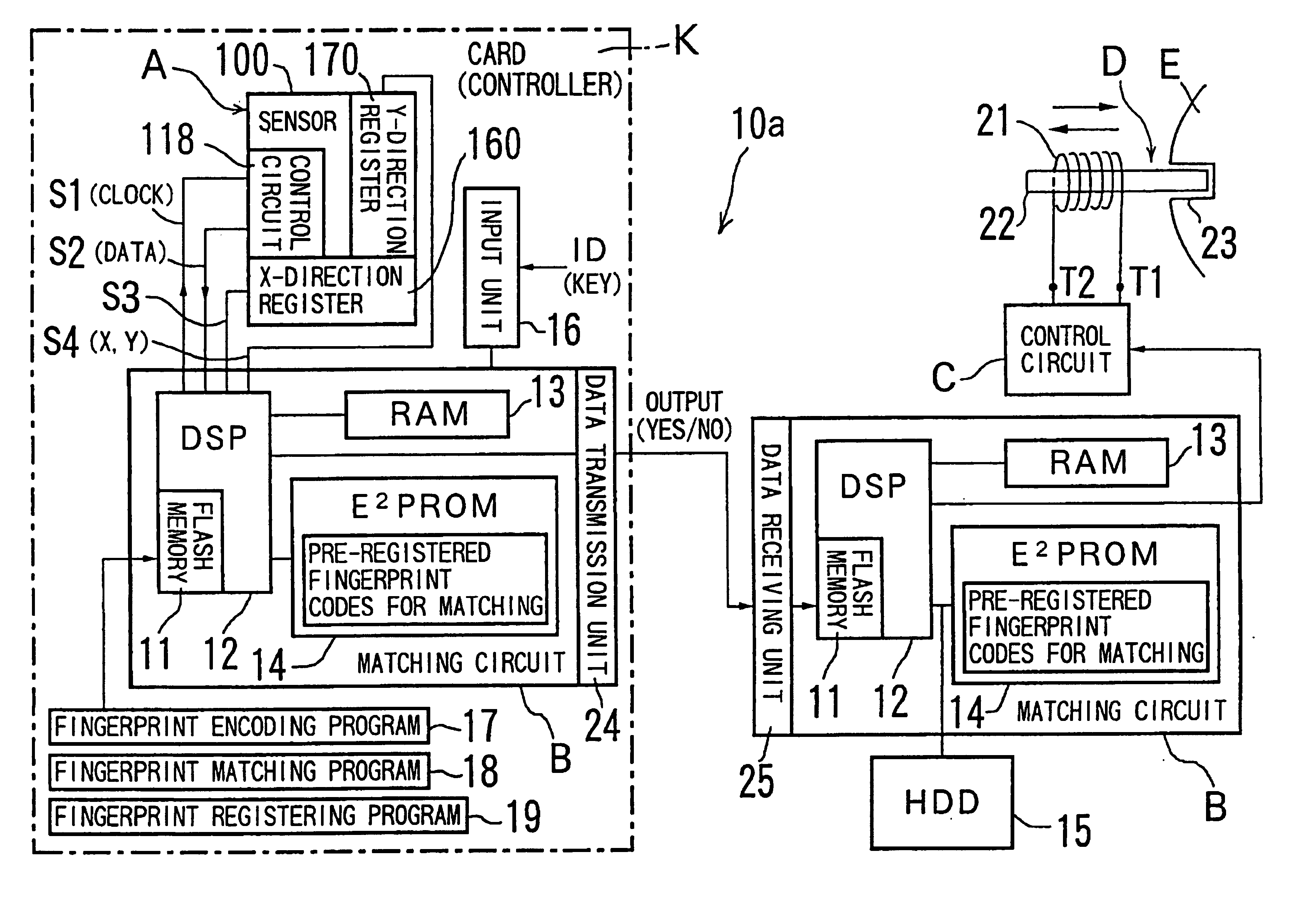
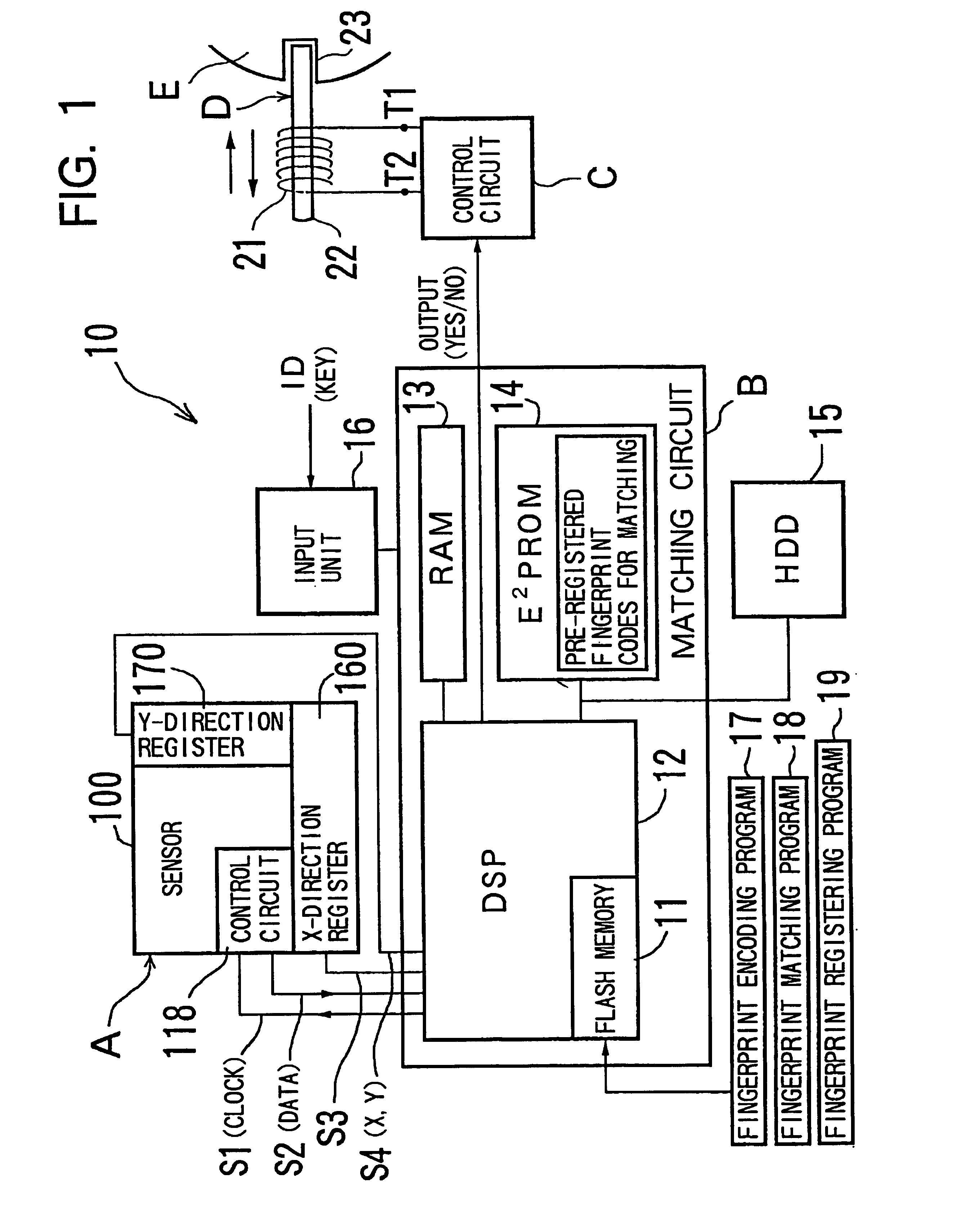
[0108]We shall now explain an example of the use of the sensor lock 10 described above. FIG. 4 shows an example of applying the sensor lock 10. FIG. 4(a) shows an example where a sensor lock 10 of the type shown in FIG. 1 is used for the doors and trunk of an automobile.
[0109]In FIG. 4(a), there is no keyhole in the doors and trunk of the car. Instead, the sensor lock 10 is installed in the door on the driver's side. The door handle 41 has the sensor unit A of the sensor lock 10. The sensor unit A is installed on the inside surface of the door handle 41 at the position where the index finger is normally placed when a person pulls the door knob towards himself, FIG. 4(b). The matching circuit B, the control circuit C, and latching solenoid D, all of the type shown in FIG. 1, are installed inside the door.
[0110]The trunk lid 42 has a door handle (not shown) for opening and closing the trunk. A sensor A is installed on the back side of this handle also. The trunk lid 42 is so construct...
example 2
[0132]FIG. 6 illustrates Example 2 of Application Mode 1. FIG. 6(a) is a case where the concerned object E of FIG. 1 is for example a door of a building, or a gate. It shows the outside view of an entrance door 45 on which the sensor lock 10 has been installed. In FIG. 6(a), the door 45 is provided with a latch bolt 46 and a rotary shaft 47 that moves the latch bolt 46 inside the door 45, and a lock equipped with a dead bolt 50. The lock is basically the same as a conventional lock. In other words, the outer knob 48 is fixed co-axially on the rotary shaft 47 and this outer knob 48 has a lever 49 that extends along a direction generally perpendicular to the shaft 47.
[0133]The lever 49 is held in a more or less horizontal initial position by a spring kept in the lock, unless an external force is applied. The latch bolt 46 sticks out of the door 45 when the lever 49 is in the initial position. On the other hand, when the lever 49 turns in the clockwise or anti-clockwise direction, the ...
example 3
[0140]FIG. 7 explains Example 3 of Application Mode 1 of the invention. This is a case where a sensor lock 10 of the type shown in FIG. 1 is used to lock a steering wheel of a car. FIG. 7(a) shows the parts around the steering wheel and FIG. 7(b) the ignition switch 52.
[0141]In FIG. 7(a), the ignition switch 52 which may be operated by the key 54 of the car, is shown installed on the right side of the steering shaft cover. When the key 54 is inserted in the ignition switch 52 and turned counter-clockwise to the “Lock” position (FIG. 7(b)), the steering wheel 53 is locked. The structure of the steering wheel lock is not much different from conventional locks of this type.
[0142]A sensor unit A of the type shown in FIG. 1 is installed near the ignition switch 52, and the matching circuit B, control circuit C and latching solenoid D are installed inside the steering shaft cover. The pin 22 of the latching solenoid D restricts turning of the key 54 in the ignition switch 52 when the stee...
PUM
 Abstract
Description
Claims
Application Information
 - R&D
- Intellectual Property
- Life Sciences
- Materials
- Tech Scout
- Unparalleled Data Quality
- Higher Quality Content
- 60% Fewer Hallucinations
Browse by: Latest US Patents, China's latest patents, Technical Efficacy Thesaurus, Application Domain, Technology Topic, Popular Technical Reports.
© 2025 PatSnap. All rights reserved.Legal|Privacy policy|Modern Slavery Act Transparency Statement|Sitemap|About US| Contact US: help@patsnap.com


