
Display with multiplexed pixels

a display and multiplexing technology, applied in the field of electronic driver circuits, can solve the problems of increasing the bandwidth requirements of the data interface by 100%, unable to achieve true 8-bit gray scale resolution, and difficult to implement debiasing

Inactive Publication Date: 2005-12-27
OMNIVISION TECH INC
View PDF6 Cites 16 Cited by
  • Summary
  • Abstract
  • Description
  • Claims
  • Application Information

AI Technical Summary

Benefits of technology

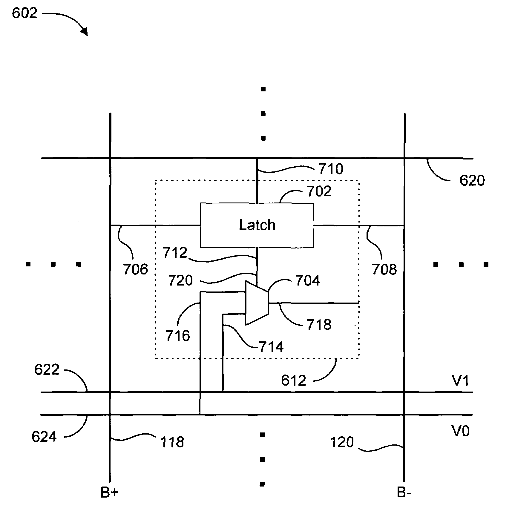
[0018]Novel methods for driving a novel display are described. In an exemplary embodiment of the display, each pixel cell includes a multiplexer for selectively coupling the pixel electrode to one of two global voltage supply terminals, responsive to a data bits stored in the pixel cell. This configuration provides many advantages over prior art displays which assert the stored data bits directly onto the pixel electrode. For example, in the present invention, the pixel electrodes can be digitally driven with voltages higher or lower than the voltages used to drive the logic circuitry of the display, thus providing flexibility with respect to the time periods that particular bits must be written to the pixel. Additionally, off states (i.e., no voltage across a pixel cell) can be written to all of the pixels of the display at one time, without changing any of the data stored in the pixel cells, by asserting appropriate voltages on the global voltage supply terminals and a common electrode overlaying the entire pixel array. Yet another advantage provided by the present invention is that the pixel cells can be debiased without the extra step of loading complementary data bits into the display, simply by asserting various predetermined voltages on the global voltage supply terminals.

Problems solved by technology

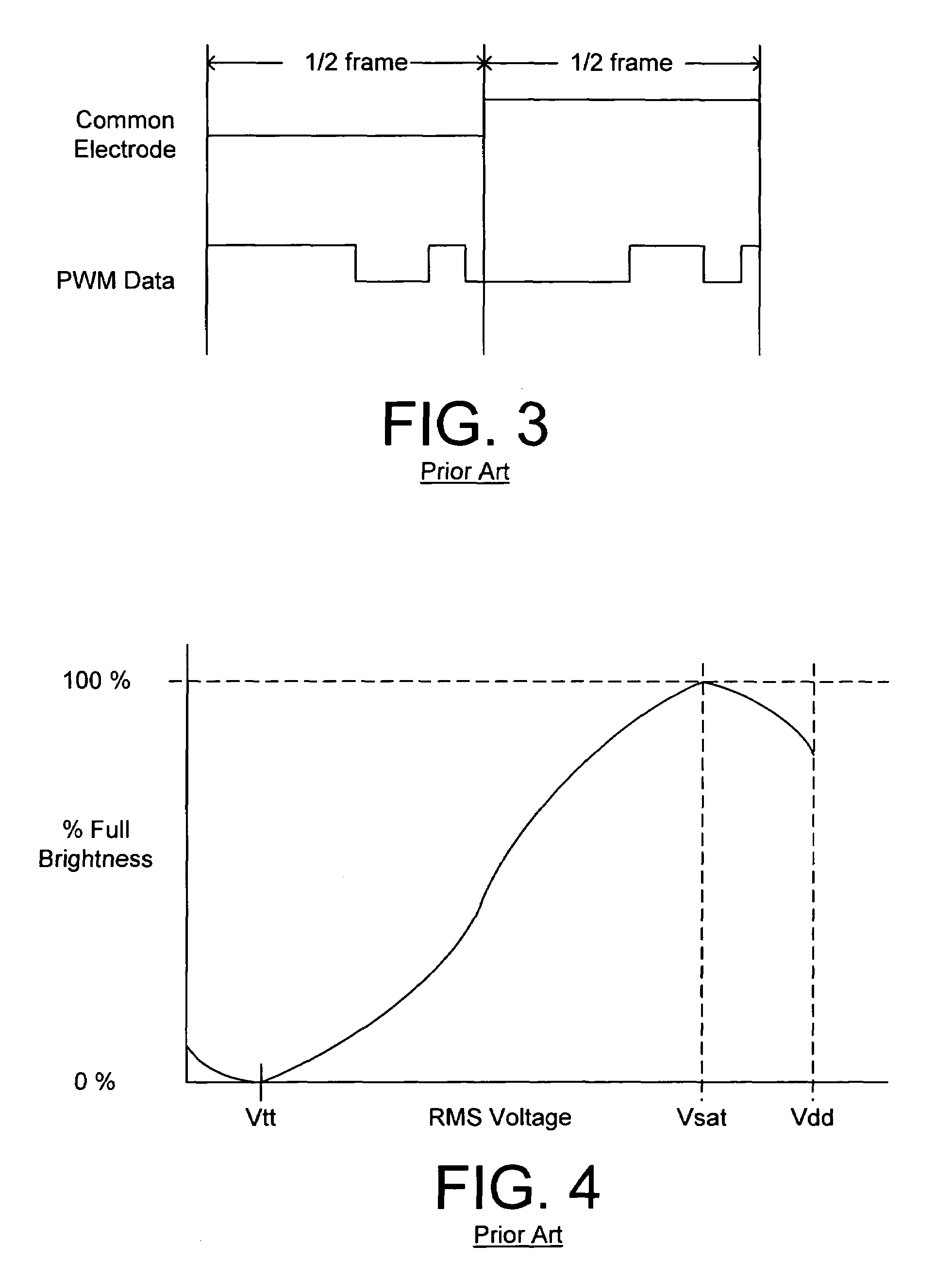
The result of these wasted values is that true 8-bit gray scale resolution is not obtained.
The addition of a single bit, however, increases the bandwidth requirements of the data interface by 100%, and is, therefore, undesirable.
In addition to the problem of confining all of the grayscale values to the useful portion of the liquid crystal response curve, it is also difficult to implement the debiasing (i.e., maintaining a net D.C. bias of 0V across the pixel cells).
Further, because of the substantial amount of time required to write data to the display, it is difficult to rapidly write an “on” state or an “off” state to the entire display.

Method used


Image

  • Display with multiplexed pixels
  • Display with multiplexed pixels
  • Display with multiplexed pixels

Examples


Embodiment Construction

[0063]The present invention overcomes the problems associated with the prior art, by using display data bits to control the multiplexing of predetermined voltages onto pixel electrodes of a display, as opposed to asserting the data bits directly on the pixel electrodes. The present invention is described with reference to particular embodiments. Numerous specific details are set forth (e.g., the number of data bits in a particular data word, the on or off chip disposition of various voltage sources, and the number of different voltage sources necessary to implement particular modulation / debias schemes) in order to provide a thorough understanding of the invention. Those skilled in the art will understand that the invention may be practiced apart from these specific details. In other instances, well known details of display driving circuits (e.g., writing data to pixel storage cells of a display) are omitted, so as not to unnecessarily obscure the present invention.

[0064]FIG. 6 shows...


PUM

PropertyMeasurementUnit
RMS voltageaaaaaaaaaa
saturation voltageaaaaaaaaaa

Abstract

A multiplexed pixel display includes a plurality of pixel electrodes, a plurality of storage elements, a first voltage supply terminal, a second voltage supply terminal, a common electrode, and a plurality of multiplexers each selectively coupling an associated one of the pixel electrodes with one of the first voltage supply terminal and the second voltage supply terminal responsive to a value of a data bit stored in an associated one of said storage elements. A controller is configured to sequentially write each bit of multi-bit data words to the storage elements, and assert, while each bit is stored in the storage elements, a first predetermined voltage on the first voltage supply terminal, a second predetermined voltage on the second voltage supply terminal, and a third predetermined voltage on the common electrode, for a time dependent on the significance of the stored bit. Various alternate controllers facilitate the use of additional driving schemes.

Description

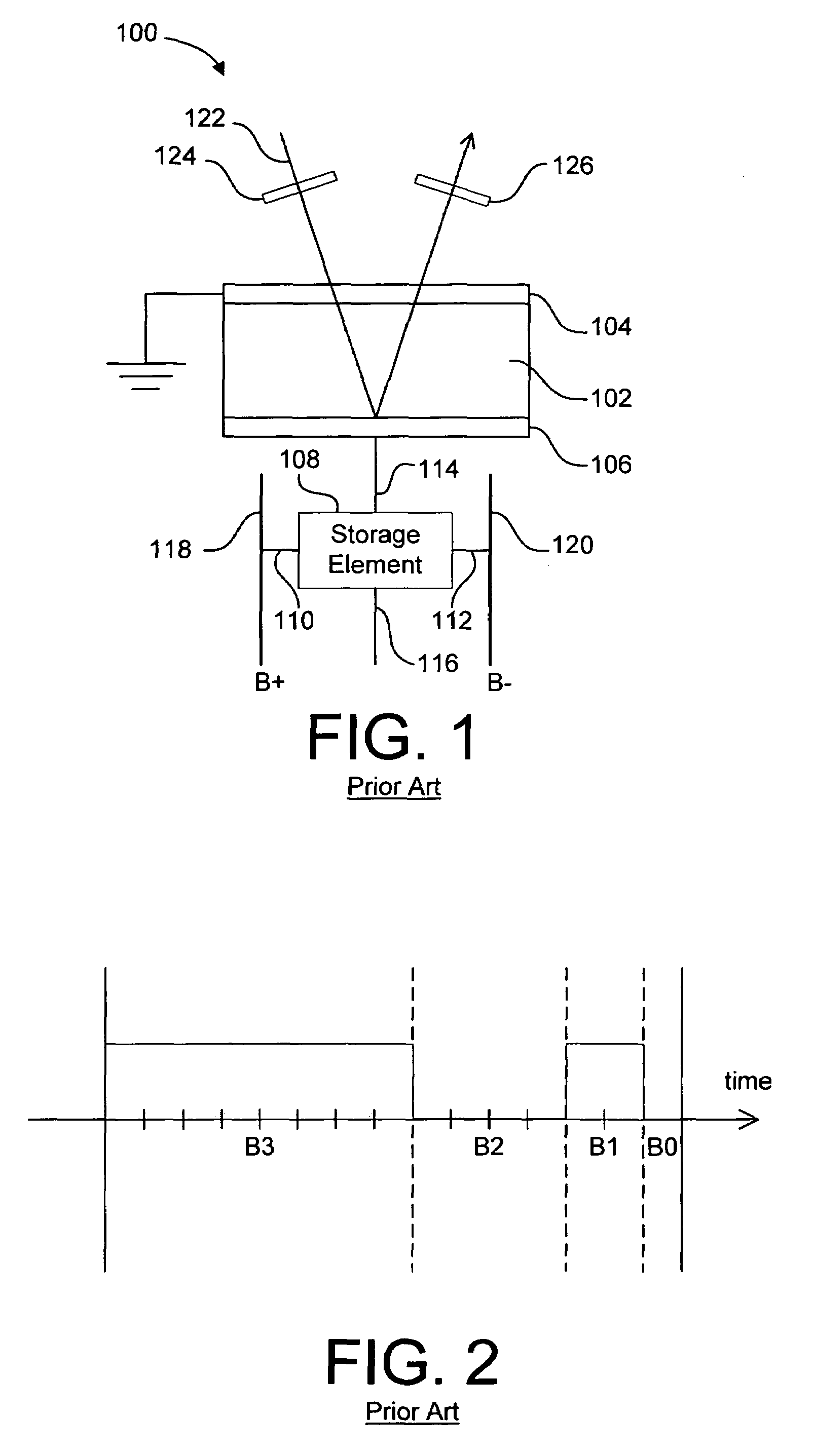
RELATED APPLICATIONS[0001]This application is a continuation of U.S. patent application Ser. No. 09 / 075,472, filed May 8, 1998 now U.S. Pat. No. 6,067,065 by the same inventors, which is incorporated herein by reference in its entirety as if fully set forth herein.BACKGROUND OF THE INVENTION[0002]1. Field of the Invention[0003]This invention relates generally to electronic driver circuits, and more particularly to a novel circuit and method for driving a display by multiplexing predetermined voltages to achieve modulation between saturation and threshold voltages of pixel electrodes in a liquid crystal display.[0004]2. Description of the Background Art[0005]FIG. 1 shows a single pixel cell 100 of a typical liquid crystal display. Pixel cell 100 includes a liquid crystal layer 102, contained between a transparent common electrode 104 and a pixel storage electrode 106, and a storage element 108. Storage element 108 includes complementary data input terminals 110 and 112, data output t...

Claims


Application Information

Patent Timeline
Patent Type & Authority Patents(United States)
IPC IPC(8): G02F1/133G09G3/20G09G3/36
CPCG09G3/3648G09G3/3659G09G3/3696G09G3/2011G09G3/2022G09G3/2025G09G3/2081G09G3/3614G09G2300/0491G09G2300/0809G09G2300/0823G09G2300/0857G09G2310/063G09G2320/0204
Inventor WORLEY, III, WILLIAM SPENCERHUDSON, EDWIN LYLECHOW, WING HONG
Owner OMNIVISION TECH INC
Learn More