Image display device for medical applications, image display method for medical applications
a technology for medical applications and display devices, applied in applications, instruments, tomography, etc., can solve problems such as difficulty in simultaneously providing information, and achieve the effect of short tim
- Summary
- Abstract
- Description
- Claims
- Application Information
AI Technical Summary
Benefits of technology
Problems solved by technology
Method used
Image

Examples
first embodiment
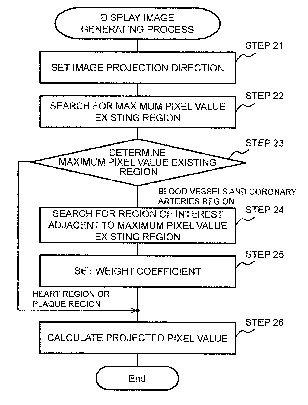
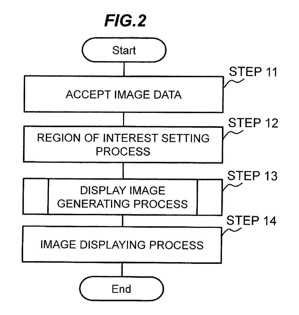
[0045]With reference to the figures from FIG. 3 to FIG. 7C, the first embodiment of the present invention will be explained. In the first embodiment, the CPU 11 in the medical image display device 1 sets a projected pixel value, by using a distance (a vascular diameter) of the region of the observation site (blood vessels and coronary arteries, etc.), and a distance of the region of adjacent lesion candidate (plaque, etc.), and generates a display image in the display image generating process of the step 13. More specifically, in the case where the pixel having a reference pixel value on the projection line of interest corresponds to the pixel in the observation site region, the CPU 11 determines a weight coefficient according to the size of the region of the adjacent lesion candidate on the projection line of interest, and sets as the projected pixel value, a value weighted the weight coefficient to the pixel value based on a group of pixels in the region of the adjacent lesion can...
second embodiment
[0070]With reference to FIG. 8, FIG. 9A, FIG. 9B, and FIG. 9C, the second embodiment of the present invention will be explained. In the second embodiment, the CPU 11 of the medical image display device 1 sets a color value in the display image generation process of the step 13, by using the change in the distance (the vascular diameter) of the region of the observation site (blood vessels and coronary arteries, etc.), the distance of the region of the adjacent lesion candidate (plaque, etc.), and the distance (the vascular diameter) of the peripheral observation site region. Then, the CPU 11 displays an image obtained by superimposing the color value on the display image in the image displaying process of the step 14. More specifically, the CPU 11 sets the reference pixel value on the projection line of interest, as a projected pixel value for the projection line of interest. When the pixel having the reference pixel value on the projection line of interest corresponds to a pixel in...
third embodiment
[0084]With reference to FIG. 10, the third embodiment of the present invention will be explained. In the third embodiment, the CPU 11 of the medical image display device 1 converts into a color value, a ratio of the pixel value corresponding to a tissue of interest (e.g., lipid) within the region of the lesion candidate (plaque, etc.), for the display image that is generated in the first embodiment, in the display image generation process of the step 13, and displays an image obtained by superimposing the color value on the display image in the image displaying process in the step 14. More specifically, in the third embodiment, the CPU 11 calculates an index value indicating a ratio of the pixels that represent the tissue of interest in the adjacent lesion candidate region on the projection line of interest, and according to the index value, the CPU 11 determines a color value of a color attribute that is different from that of the projected pixel value.
[0085]As shown in FIG. 10, th...
PUM
 Abstract
Description
Claims
Application Information
 - R&D
- Intellectual Property
- Life Sciences
- Materials
- Tech Scout
- Unparalleled Data Quality
- Higher Quality Content
- 60% Fewer Hallucinations
Browse by: Latest US Patents, China's latest patents, Technical Efficacy Thesaurus, Application Domain, Technology Topic, Popular Technical Reports.
© 2025 PatSnap. All rights reserved.Legal|Privacy policy|Modern Slavery Act Transparency Statement|Sitemap|About US| Contact US: help@patsnap.com