
Apparatus for inserting particles into tissue, in particular muscle tissue

Inactive Publication Date: 2005-12-27
ABBOTT CARDIOVASCULAR
View PDF12 Cites 12 Cited by
  • Summary
  • Abstract
  • Description
  • Claims
  • Application Information

AI Technical Summary

Benefits of technology

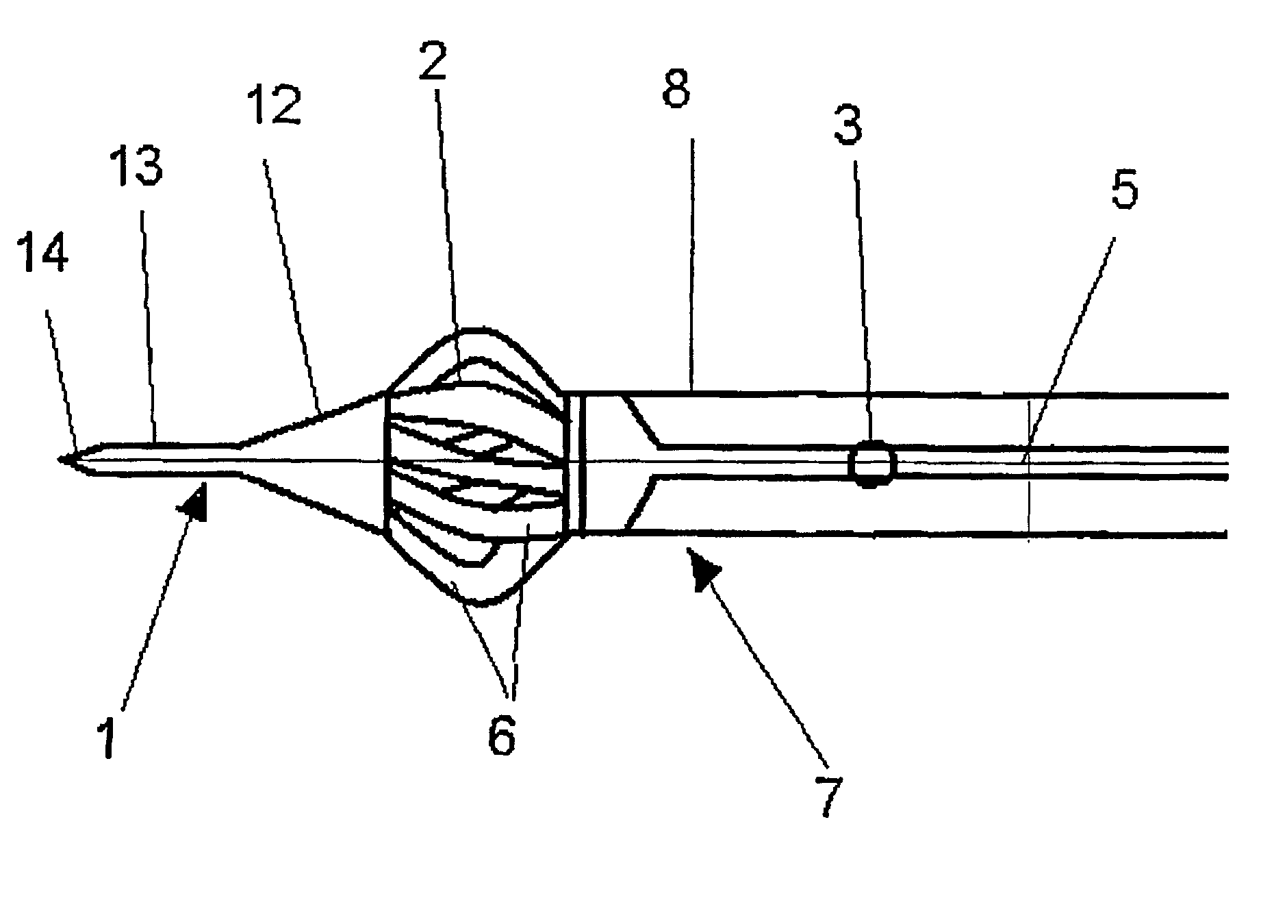
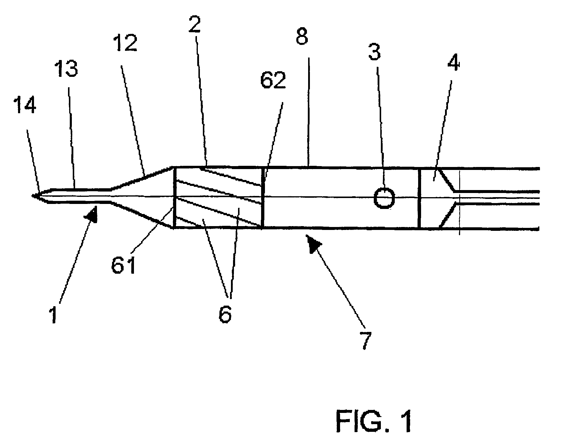
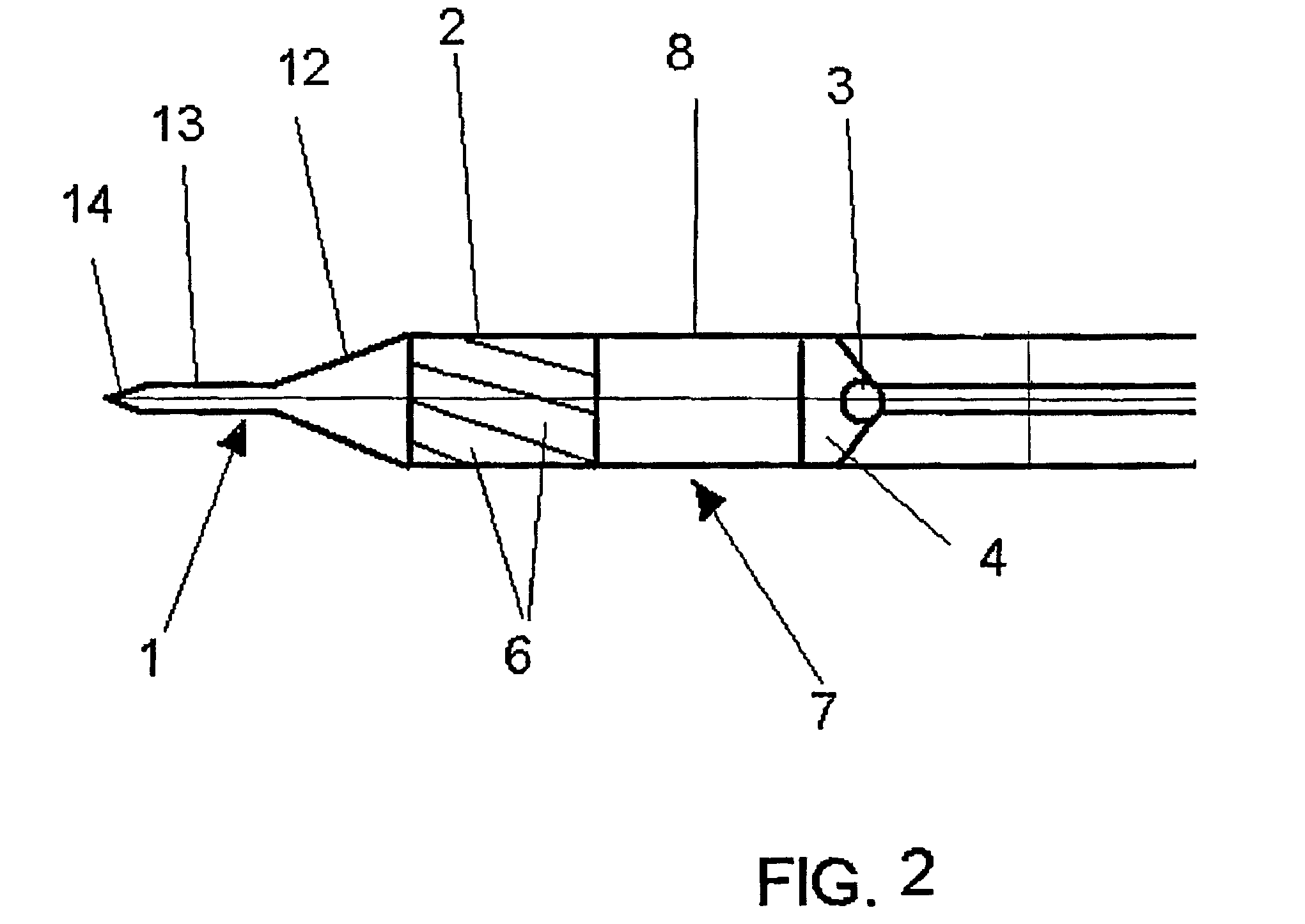
[0009]The positioning element serves for positioning the apparatus and facilitates the penetration into the tissue, where it is thereby affixed. In the tubular body a space is formed between the end of the positioning element, averted to the distal end of the apparatus, and the thrust means, which serves for receiving the particles to be introduced into the tissue. If the apparatus is brought into a tense condition, which will be described later in detail, the outlet area is extended in the radial direction, whereby openings, through which the particles can emerge out of the space described above and can penetrate into the tissue, are formed between the flexible elements forming this area.
[0011]Preferably the positioning element is a needle tip. This needle tip can ensure a rapid insertion of the apparatus into the tissue and can thus avoid a sideslip, as it would occur with an apparatus, where the insertion would take place slowly. According to the invention, the needle tip can have a tapered portion, which extends from the outlet area to the distal end of the apparatus. In such an embodiment, the length of the tip must be chosen accordingly, in order to achieve a small increase in diameter from the distal end to the outlet area over small axial distances. If the increase of the diameter over small axial distances would be too large, the insertion into the tissue would be more difficult.
[0014]The elements of the outlet area can have different shapes. In one embodiment the elements are formed as stripes of a flexible material and are arranged in a spiral or helical arrangement. With such a helical arrangement of the elements, their flexibility can be sustained. An ideally formed basket can form with such a helical arrangement in the tense condition, if the elements are attached on both sides, i.e., towards the sleeve and the positioning element. At the position of the largest diameter, this basket exhibits the biggest distances between the stripe-shaped elements and in addition exhibits a high stability. Especially, if the apparatus should be used for inserting particles into a cardiac muscle or any other strong muscle tissue, it is important that this area exhibits a stability, which can withstand the external pressure applied on the outlet area and can ensure an expansion of the tissue.
[0016]In the relaxed condition, the outlet area forms a closed area, i.e., the elements abut close to each other or overlap. In order to ensure the sealing of this area and to thereby prevent escaping of smaller particles during the insertion of the apparatus into the tissue, the apparatus can also have two layers of elements. These two layers are preferably formed as tubes and are radially spaced from each other. In this embodiment, the direction of the spiral winding of the elements of the inner layer can be opposite to the direction of the spiral winding of the elements of the outer layer. It is also possible to provide different angles of inclination of the spiral windings in the two layers. By providing two layers, two tubular walls for the outlet area are formed, which prevent an undesired early escape of particles.
[0025]Basically those catheters, which are already known, can be used as catheters. The design of catheters, as well as their handling, is known in the field of medical engineering and will therefore not be further explained at this point. The catheter for the inventive apparatus, however, exhibits at its distal end the components of the apparatus, in particular the positioning element and the outlet area. The guide catheter encloses the catheter, which carries the apparatus or represents the apparatus, respectively, and serves for an easier insertion of the inner catheter into the vessels and prevents the occurrence of injuries or irritations, which can occur due to the back-and forth-movement of the inner catheter, e.g., for tensioning and relaxing the apparatus.
[0026]Before the apparatus is inserted into the tissue and first into the vessel leading to the location to be treated, respectively, the apparatus will be loaded with the corresponding particles, e.g., pharmaceuticals, cell cultures in the form of pellets, etc. For this purpose the apparatus preferably has a charging port, which is provided in the wall of the sleeve spaced from the outlet area. Via this charging port the particles can be brought close to the outlet area, which is of special interest for apparatus, which represent catheters and can accordingly be of considerable length. If for example cell cultures shall be brought into the cardiac muscle, the catheter will have a length of about one meter and at the same time the cell cultures are sensitive substances, which can be damaged by a long residual time in the catheter and by too frequent contacting with and rubbing along the walls of the catheter. In particular in such applications the providing of a charging port close to the outlet area will be of advantage.

Problems solved by technology

These apparatus are, however, disadvantageous in that, as soon as the apparatus is withdrawn from the drilled channel, the tissue can only contract itself to a limited extent and thus the particles can escape from the channel.
If no channel is drilled there is not sufficient space for the particles in the tissue.
Furthermore with tissues, which are in constant motion, such as the tissue of the cardiac muscle, it is difficult to position and affix the apparatus for the insertion of the particles.

Method used


Image

  • Apparatus for inserting particles into tissue, in particular muscle tissue
  • Apparatus for inserting particles into tissue, in particular muscle tissue
  • Apparatus for inserting particles into tissue, in particular muscle tissue

Examples


Embodiment Construction

[0034]In FIG. 1 an embodiment of the apparatus 10, according to the invention, is shown schematically. The apparatus 10 has at its distal end a positioning element 1. This element 1 is represented by a needle tip. In the embodiment, as shown, the needle tip comprises a portion 12, which is tapered in the direction of the distal end, an adjacent cylindrical portion 13 of small diameter and finally a needlepoint 14, which runs to a point at the distal end. Adjacent to this positioning element 1 is an outlet area 2. This area 2 shows a plurality of elements 6, which in the embodiment as shown are arranged diagonal to the axis of the tubular body 7 and which form a closed superficies. The elements 6 are connected at their one end 61 with the positioning element 1 and at their other end 62 with the sleeve 8. The sleeve 8 extends in axial direction to any length. At the axial end of the sleeve 8, which is opposite to the end adjacent to the outlet area, an actuating device (not shown) is ...


PUM


Abstract

An apparatus for inserting particles (P) into a tissue (G), in particular a muscle tissue, wherein the apparatus (10) essentially represents a tubular body (7) with one closed end and comprises at least one sleeve (8), at least one positioning element (1), at least one outlet area (2), which extends over the entire circumference of the tubular body (7), at least one thrust means (4) for the particles (P), as well as an actuating device for the outlet area (2), and wherein the outlet area (2) is formed by a plurality of flexible elements (6), which are at least attached to the sleeve (8), which butts against the outlet area (2) in the axial direction, or the positioning element (1) in such a way, that in a tense condition the diameter of the outlet area (2) is larger than the diameter of the sleeve (8), and openings are present between the elements (6).

Description

CROSS-REFERENCE TO RELATED APPLICATION[0001]Applicant hereby claims priority based on German Utility Model Registration No. G 200 12 003.4 filed Jul. 11, 2000, entitled “Apparatus for Inserting Particles into Tissue, in Particular Muscle Tissue” which is incorporated herein by reference.FIELD OF INVENTION[0002]The present invention relates to an apparatus for inserting particles into a tissue, in particular muscle tissue.[0003]For example, for administering medicine or for inserting cell cultures in the body of a human being or an animal, it can be necessary to introduce those agents, which were only recited as examples and will hereinafter generally be referred to as particles, directly into the tissue. For treatment of the heart it can even be necessary to insert the particles directly into the cardiac muscles.BACKGROUND OF THE INVENTION[0004]Apparatus are already known, which cut channels into the tissue, in order to provide a space for the reception of the particles. These appar...

Claims


Application Information

Patent Timeline
IPC IPC(8): A61B17/00A61B17/34A61M25/00A61M37/00
CPCA61M37/00A61B17/3478A61B2017/00247A61B2017/00986A61B2017/3488A61B2018/00392A61M25/0068A61M25/0074A61M2025/0079A61M2210/125
Inventor GEIS, JOHN S.BRAUN, MICHAEL
Owner ABBOTT CARDIOVASCULAR
Learn More